

Isostatic press
- Summary
- Abstract
- Description
- Claims
- Application Information
AI Technical Summary
Benefits of technology
Problems solved by technology
Method used
Image

Examples
first embodiment
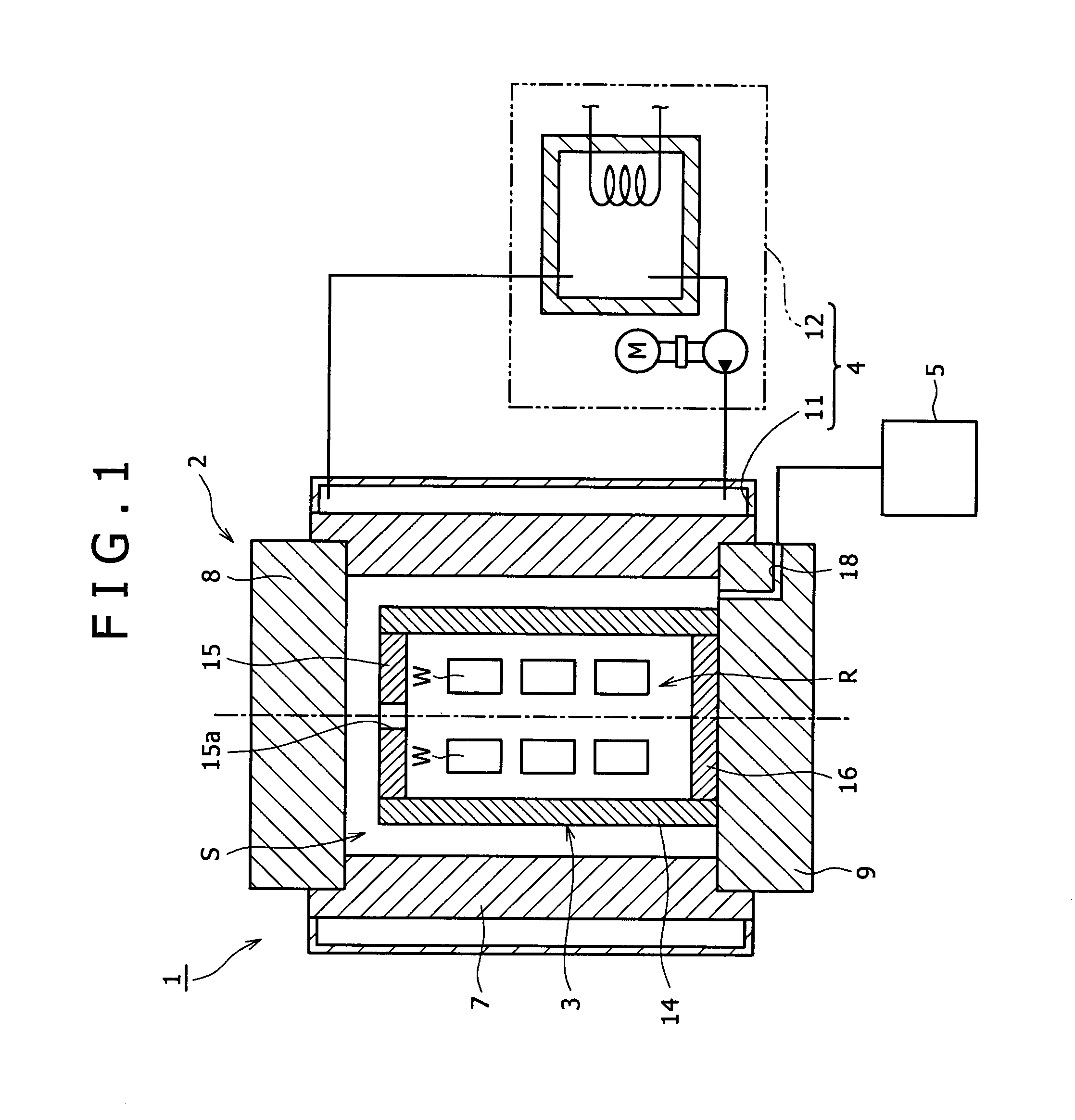
[0030]An isostatic press 1 according to the present embodiment is used for warm isostatic pressing which carries out a processes in which an isostatic pressure is applied via a pressure medium in a temperature range from 100° C. to 300° C. to a workpiece W. The isostatic press 1 includes a high pressure vessel 2, a heat insulator 3 which is stored within the high pressure vessel 2, a heating unit 4 which heats the high pressure vessel 2, and a pressure medium supplying device 5 which introduces the pressing medium inside the high pressure vessel 2, as shown in FIG. 1.
[0031]The high pressure vessel 2 includes a cylindrical vessel 7 which is formed thick, and an upper closure 8 and a lower closure 9 which detachably close respectively top and bottom openings of the vessel 7 in a liquid tight manner. The pressurized container 2 is formed as a hollow column as a whole.
[0032]Though upward and downward axial forces are applied respectively to the upper closure 8 and the lower closure 9 by...
second embodiment
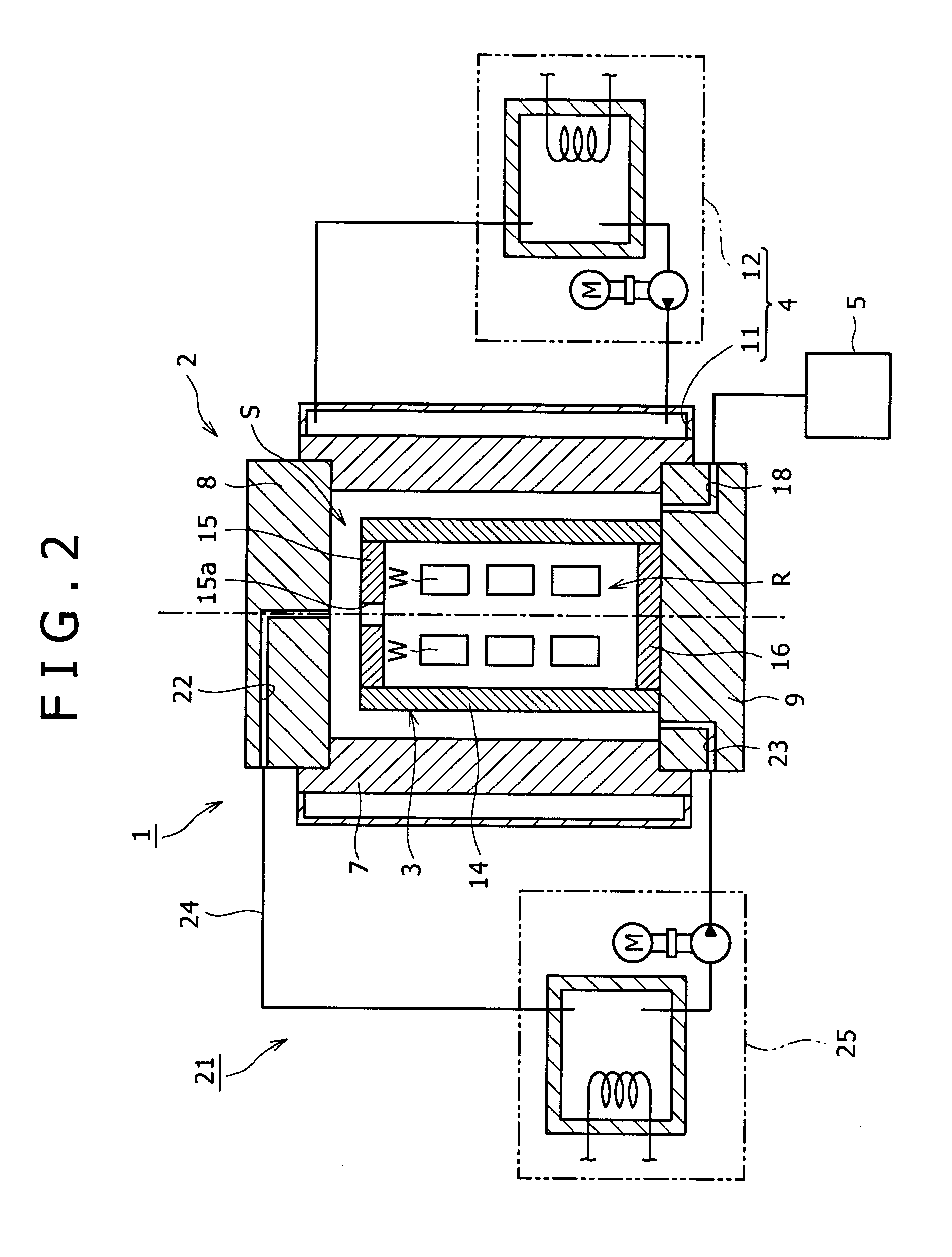
[0051]According to the present embodiment, the pressure medium introducing space S is connected to a pressure medium circulating device 21 which circulates the pressure medium inside the pressure medium introducing space S as shown in FIG. 2.
[0052]The pressure medium circulating device 21 includes a pipeline 24. The pipeline 24 includes a pressure medium outflow pipe 22 which is formed in the upper closure 8, and communicates with the pressure medium introducing space S at a position opposing to the through hole 15a in the top heat insulating closure 15, and a pressure medium inflow opening 23 which is formed in the lower closure 9, and communicates with the bottom end portion of the pressure medium introducing space S. A heating device 25 for heating the pressure medium passing the pipeline 24 is provided in the course of the pipeline 24.
[0053]According to the present embodiment, the pressure medium is heated by the heating device 25 while the pressure medium in the pressure medium...
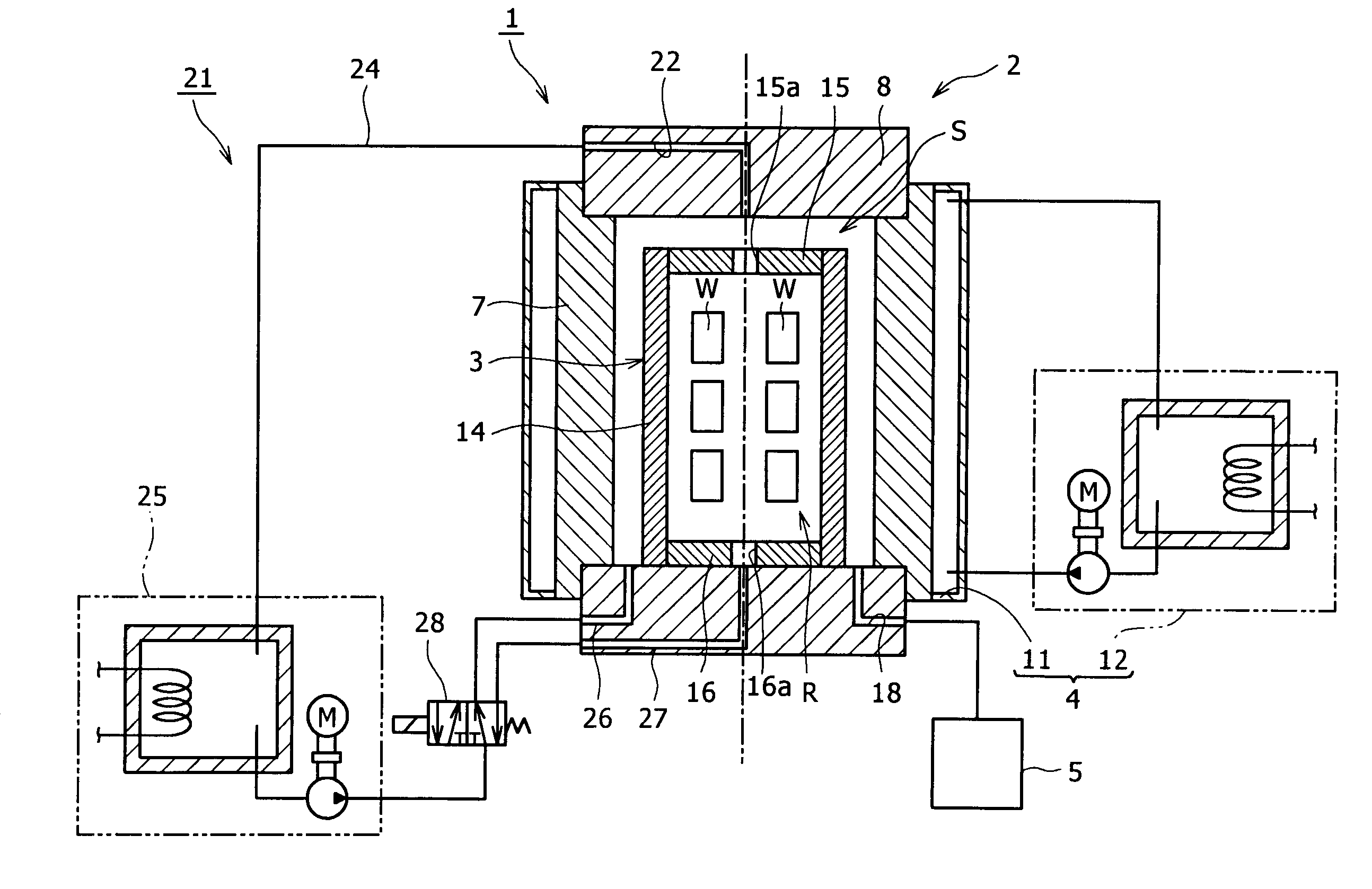
third embodiment
[0055]As shown in FIG. 3, in the present embodiment, the pressure medium circulating device 21 includes a first pipeline 26 which can introduce the pressure medium heated by the heating device 25 into the pressure medium introducing space S, a second pipeline 27 which can introduce the pressure medium into the working zone R, and a selector valve 28 which can switch a state where the pressure medium is supplied to one of the pipelines 24 to a state where the pressure medium is supplied to the other one of the pipelines 24.
[0056]The bottom heat insulating closure 16 includes a through hole 16a which passes through from the inside to the outside of the working zone R on the center axis passing vertically at the center of the working zone R at a position corresponding to the through hole 15a in the top heat insulating closure 15. The second pipeline 27 communicates with the through hole 16a.
[0057]According to the present embodiment, it is possible to introduce the pressure medium heat...
PUM
| Property | Measurement | Unit |
|---|---|---|
| Temperature | aaaaa | aaaaa |
| Pressure | aaaaa | aaaaa |
Abstract
Description
Claims
Application Information