Duct Tape Dispenser

Inactive Publication Date: 2007-11-22
WENDY STEELE +1
View PDF23 Cites 16 Cited by
  • Summary
  • Abstract
  • Description
  • Claims
  • Application Information

AI Technical Summary

Benefits of technology

[0010]The dispenser is self-standing in a manner that makes it easy to grasp the roll while preventing the tape from rolling away, and it is conspicuous, reducing the likelihood that the roll of tape will be misplaced. In a further form of the invention, the dispenser has exterior magnets for conveniently storing the dispenser on a metal or magnetic surface. In a further preferred form, the sidewalls of the dispenser have flat outer surfaces to permit stacking (vertically or ho

Problems solved by technology

These cutters do not appear to have the ability to catch and hold the cut end of tape.
As such they appear to be lightly built, with open housings or thin, flexible members that make them easy to reload with a fresh roll of tape, but that in our opinion make them unsuitable or undesirable for dispensing and cutting one of the most popular and widely used rolls of tape found today in the average household or workshop: duct tape.
Anyone who has used duct tape, known for its width and sticky strength, has

Method used


Image

  • Duct Tape Dispenser
  • Duct Tape Dispenser
  • Duct Tape Dispenser

Examples


Embodiment Construction

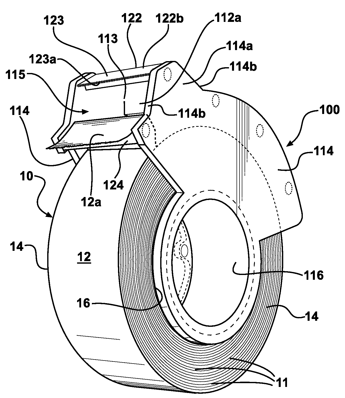
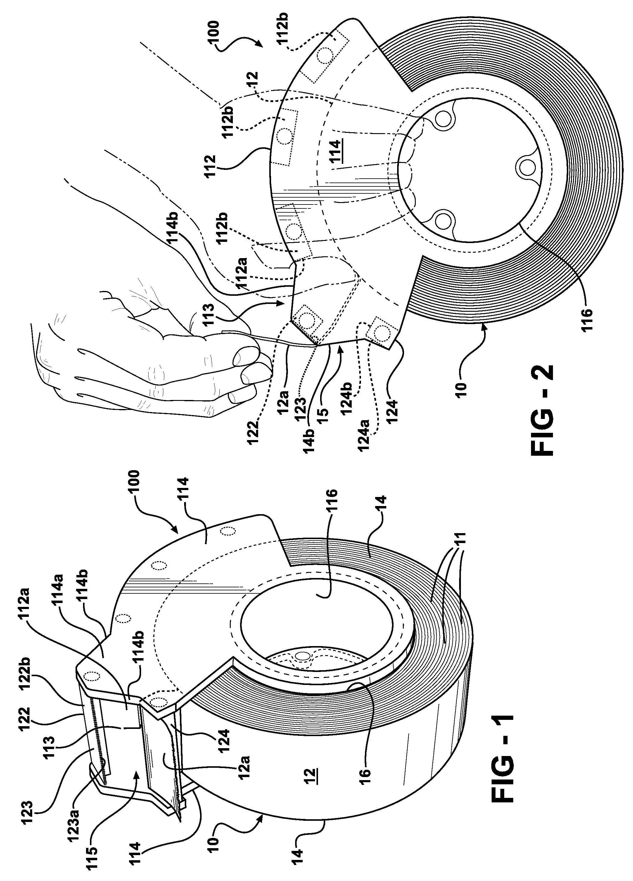
[0020]Referring to FIGS. 1 and 2, a common roll of duct tape 10 (most commonly gray, two or three inches wide, heavy, waterproof, hard to tear, possibly reinforced, and sometimes—perhaps originally—called “duck” tape) is shown held in a dispenser 100 according to a preferred example of the present invention. Roll 10 is formed in known manner from multiple layers of tape 11 wound around a spool 16, the spool usually being made of cardboard although other materials are possible. The roll has a top or outer surface 12 consisting of the outermost layer of tape, sides 14 formed by the multiple thicknesses of wound tape (and the spool edges), and an inner diameter or surface 16a (FIG. 5) which is the inner wall of spool 16.

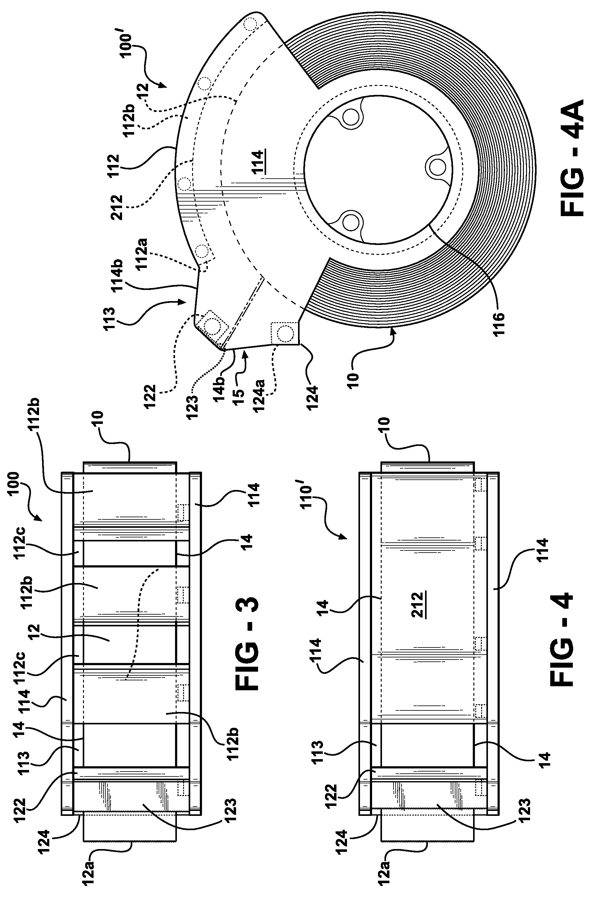
[0021]Dispenser 100 has a top wall portion 112 spaced from and generally following the curvature of the outer surface 12 of roll 10; sidewalls 114 spaced from and generally parallel to roll sides 14; and a spool support 116 extending from one dispenser sidewall 114 thro...


PUM

PropertyMeasurementUnit
Widthaaaaaaaaaa
Ferromagnetismaaaaaaaaaa

Abstract

A tape dispenser, useful for storing, dispensing, and cutting a roll of duct tape, or similar wide, heavy, hard-to-tear tape. The dispenser has a unique roll-surrounding structure with two sidewalls, a top wall axially extending between the sidewalls above the roll of tape, a spool support extending axially between the sidewalls and through the roll's spool, a retainer bar extending axially between the sidewalls, and an elevated cutting bar located above the top wall and the retainer bar and extending axially between the sidewalls. The dispenser is formed in two axially separable halves. The retainer and cutting bars help connect and strengthen the sidewalls, and are in turn reinforced by the sidewalls and the rest of the dispenser in their tape-retaining and cutting functions. The rigid, axially separable halves of the dispenser are preferably held together with a magnetic connection. The dispenser can also include a bracket that both removably stores the dispenser on the undersurface of a cabinet or the like, and that allows tape to be dispensed and torn with one hand from the bracket-mounted dispenser.

Description

FIELD OF THE INVENTION[0001]The present invention is in the field of dispensers for pressure-applied adhesive tape.BACKGROUND OF THE INVENTION AND DESCRIPTION OF RELATED ART[0002]Dispensers for large rolls of tape have been known for many years. Most seem to be designed for packaging tape. While professional packagers often use heavy, handle-equipped dispensers that look somewhat like large handguns, most dispensers for the average user seem to have split arms that bracket the sidewalls of the roll, with curved or cylindrical spool supports extending inwardly from the split arms into the tape's spool to rotationally support the roll between the arms. The arms extend away from the surface of the roll, and a cutting element is held between the ends of the arms away from the roll, the cutting element oriented generally parallel to the tape-feed direction. The arms typically have spaced guide / retainer tabs associated with the cutting element, apparently to either help direct the tape to...

Claims


Application Information

Patent Timeline
IPC IPC(8): B44C7/00
CPCY10T156/1795B65H35/0026
Inventor STEELE, RICHARD W.STEELE, WENDY
Owner WENDY STEELE
Why Eureka
Try Eureka