Apparatus and methods for mounting flat panel displays

a technology of flat panel display and apparatus, which is applied in the field of electronic displays, can solve the problems of reducing the active image area of the display available for displaying information, reducing the economic value of fpds with the four corners removed or rounded, and reducing the available active so as to maximize the available image area of the display, the effect of minimizing the display profil

Inactive Publication Date: 2007-11-22
TANNAS JR LAWRENCE E
View PDF15 Cites 32 Cited by
  • Summary
  • Abstract
  • Description
  • Claims
  • Application Information

AI Technical Summary

Benefits of technology

[0012] In an exemplary embodiment, an existing display may be removed from the panel opening before mounting the frame to the outer surface of the control panel. The new display may have an active area that is greater than the existing display, e.g., thereby increasing and / or maximizing the size of the display given the fixed area available on the control panel.
[0018] The apparatus may also include a bezel or frame for securing the display to the bracket such that the display at least partially covers the panel opening. For example, the display may have dimensions larger than the panel opening such that the display covers both the panel opening and any fasteners or holes adjacent the panel opening. In an exemplary embodiment, the bezel and bracket are pivotally attached to one another, e.g., along one edge of the bezel and bracket. Optionally, the bezel and / or bracket may include interlocking elements, a latch, or other lock for securing the bezel against the bracket, e.g., such that the bezel and bracket lie substantially parallel to one another and / or to the control panel. Thus, the apparatus may minimize a profile of the display, e.g., how far the display protrudes from the surface of the control panel, while maximizing the available image area of the display given the limited size of an existing panel opening in a control panel.

Problems solved by technology

FPDs, however, may not be made economically with the four corners removed or rounded, e.g., due to the external circuits extending along at least two edges of the displays.
Consequently, if a square or rectangular display is to be mounted within a panel opening, the display must be smaller than the panel opening, which may substantially reduce the active image area of the display available for displaying information.
Once the box is mounted, however, it may be difficult to make any necessary connections between the box and the FPD and / or to secure the FPD to the control panel.

Method used


Image

  • Apparatus and methods for mounting flat panel displays
  • Apparatus and methods for mounting flat panel displays
  • Apparatus and methods for mounting flat panel displays

Examples


Embodiment Construction

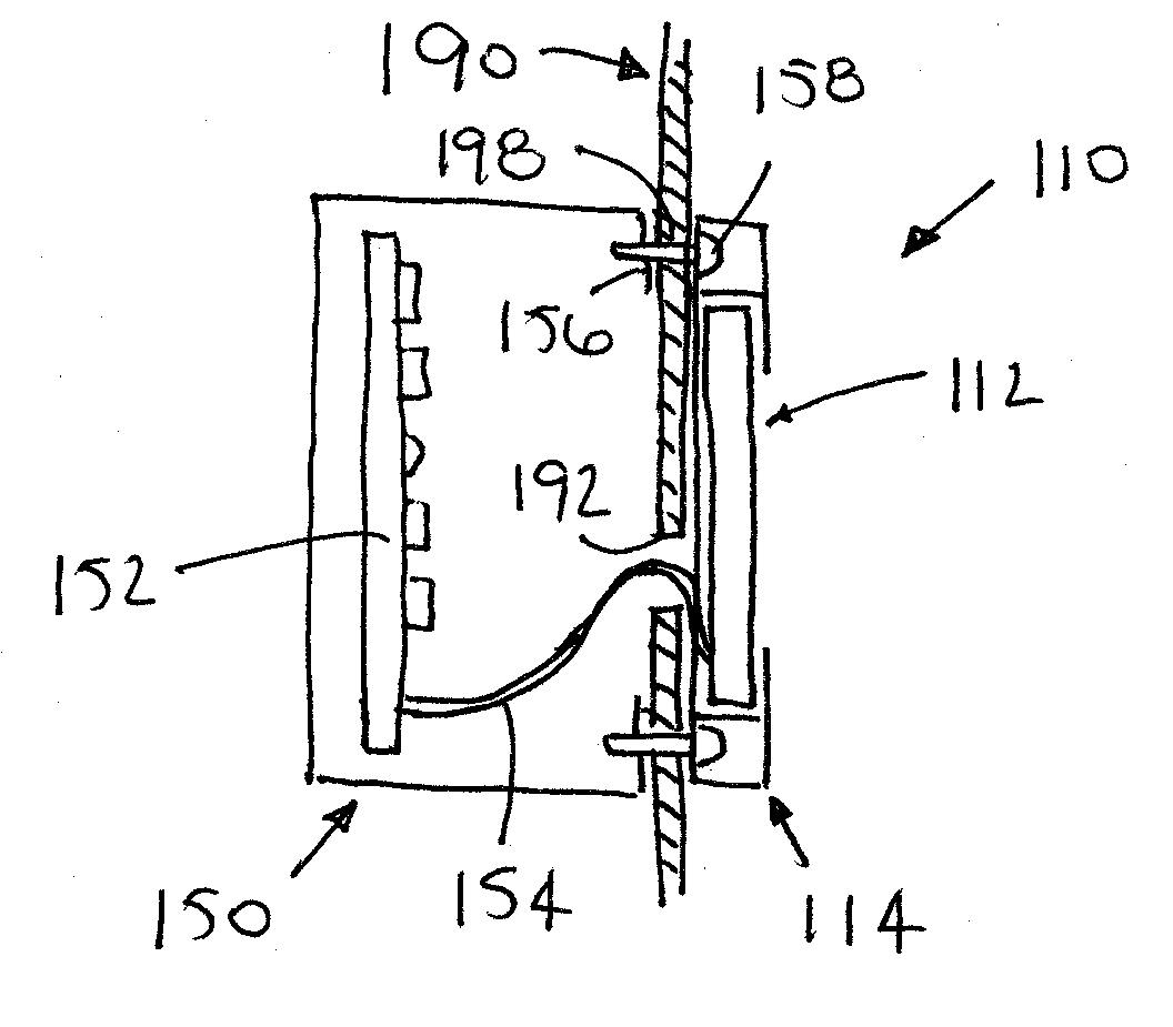
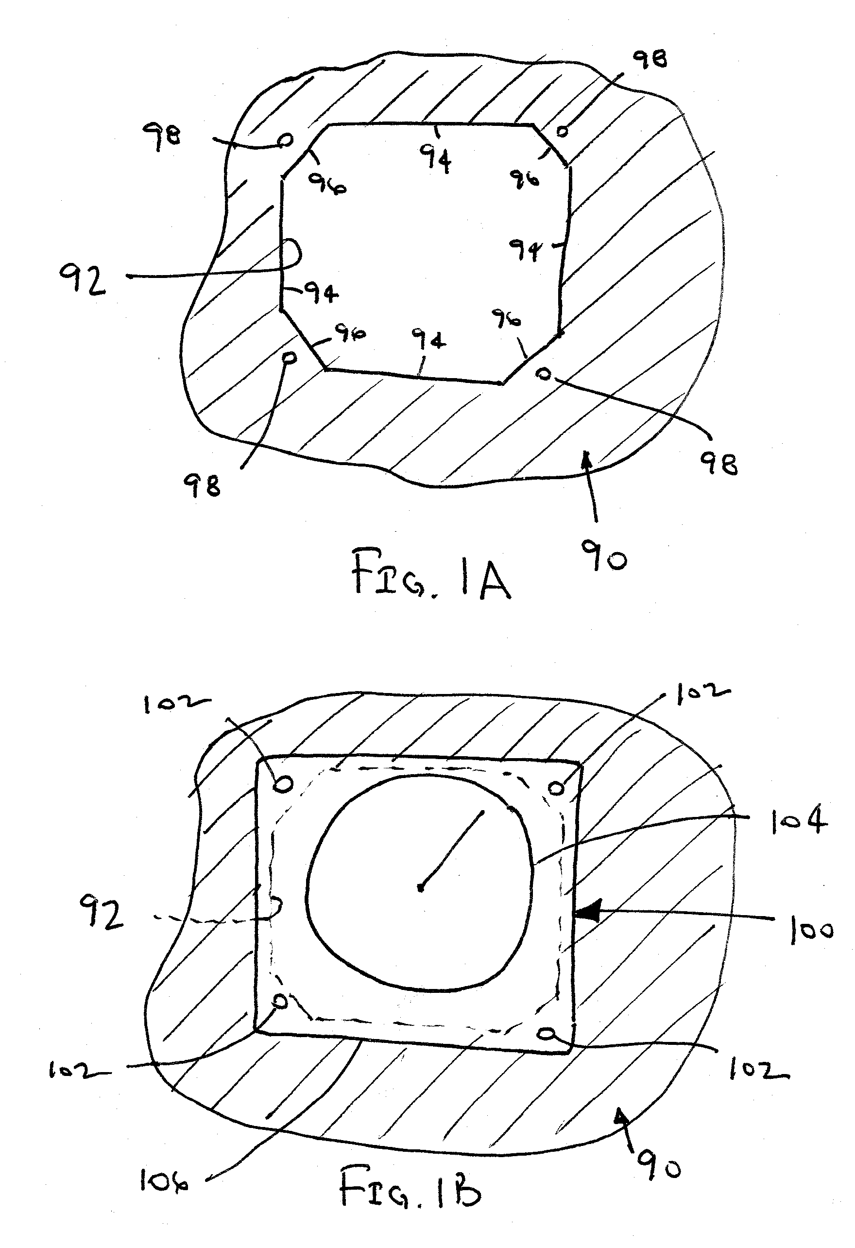
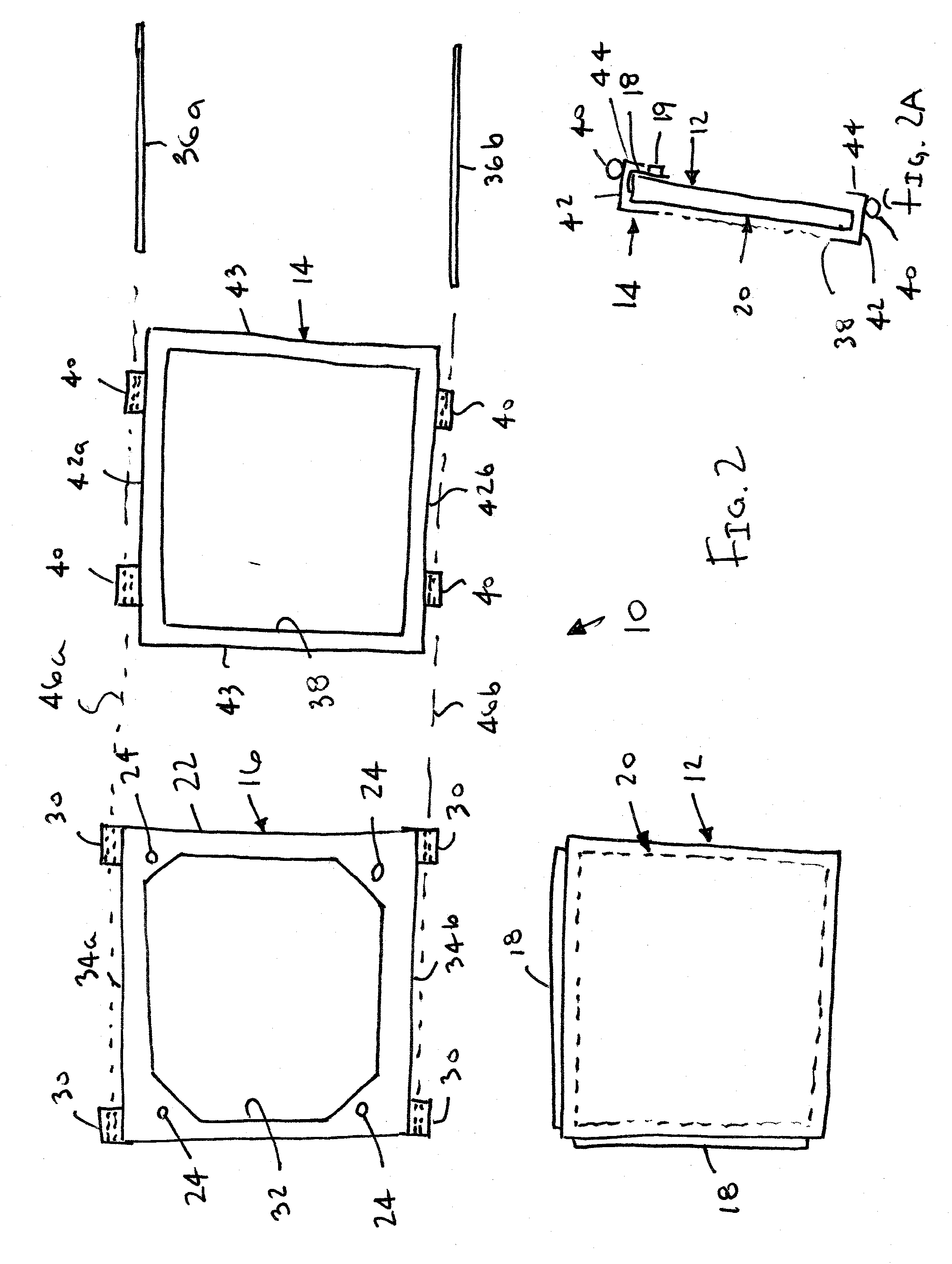
[0037] Turning to the drawings, FIG. 2 shows an exemplary embodiment of an apparatus 10 that generally includes a flat panel display (“FPD”) 12, a bezel or other frame 14 for receiving the display 12, and a bracket 16 for mounting the bezel 14 and / or display 12 to a control panel, such as the control panel 90 shown in FIG. 1A.

[0038] The display 12 may be a liquid crystal display (“LCD”), such as an active matrix liquid crystal display (“AMLCD”). It will be appreciated that the display 12 may include other types of electronic displays, such as plasma displays, liquid crystal on silicon (“LCOS”) displays, and the like. The display 12 may have a rectangular, square, or other size and / or shape, which may be larger than a cross-section of the panel opening 92 in the control panel 90, as explained further below. Optionally, the display 12 may be a resized display, i.e., a rectangular display that has been cut and resealed into a smaller configuration, e.g., a square or other configuratio...


PUM


Abstract

Apparatus and methods are provided for mounting a flat panel display to an outer surface of a control panel over a panel opening therein, e.g., for retrofitting an existing display. A display is secured to a frame, and the frame is mounted to the control panel such that the display is disposed over the panel opening. Wires from the display are directed through the control panel, and coupled to circuitry behind the control panel. For example, a box with circuitry to operate the display may be mounted behind the control panel, e.g., generally opposite the display. The display may be a resized liquid crystal display, e.g., including one or more diagonal corners. The resulting display may be larger than the existing display and / or may maximize the size of an active area of a display given a fixed area available on a control panel.

Description

RELATED APPLICATION DATA [0001] This application is a continuation-in-part of co-pending application Ser. No. 11 / 049,621, filed Feb. 2, 2005, which claims benefit of provisional application Ser. No. 60 / 541,148, filed Feb. 2, 2004, the entire disclosures of which are expressly incorporated by reference herein.FIELD OF THE INVENTION [0002] The present invention relates generally to electronic displays for displaying information, and to apparatus and methods for mounting a display to a panel, such as a control panel within a cockpit of an aircraft, flight simulator, or work station. BACKGROUND [0003] Control panels, e.g., provided within a cockpit of an aircraft, include a plurality of panel openings for receiving instruments therein. FIG. 1A shows an exemplary panel opening 92 that may be provided in a control panel 90 and having an octagonal shape, e.g., a generally rectangular or square shape defined by vertical and horizontal sides 94 but with diagonal corners 96. Generally, holes ...

Claims


Application Information

Patent Timeline
Patent Type & Authority Applications(United States)
IPC IPC(8): H04N5/64
CPCB60K35/00B60K2350/405B64D43/00B60R11/0235B60Y2304/076B60K2350/941B60K2370/67B60K2370/81
Inventor TANNAS, LAWRENCE E. JR.
Owner TANNAS JR LAWRENCE E
Why Eureka
Try Eureka