Mobile transforming plug

a plug and transforming technology, applied in the field of plugs, can solve the problems that the prior art providing the transforming-linking function for telephone lines or internet lines does not meet the requirements of the manufacturers of these electronic information products, and cannot be plugged and connected with electronic information products, so as to achieve the effect of simplifying components and smart structur

Inactive Publication Date: 2007-11-22
LIAO SHENG HSIN
View PDF2 Cites 2 Cited by
  • Summary
  • Abstract
  • Description
  • Claims
  • Application Information

AI Technical Summary

Benefits of technology

[0006] One particular aspect of the present invention is to provide a mobile transforming plug. The present invention provides the plug with a smart structure. The plug is portable and i...

Problems solved by technology

However, the mobile telephone line connection base of the prior art only provides the transforming-linking function for telephone lines or Internet lines.
It cannot be plugged and connected with electronic information pro...

Method used


Image

  • Mobile transforming plug
  • Mobile transforming plug
  • Mobile transforming plug

Examples


first embodiment

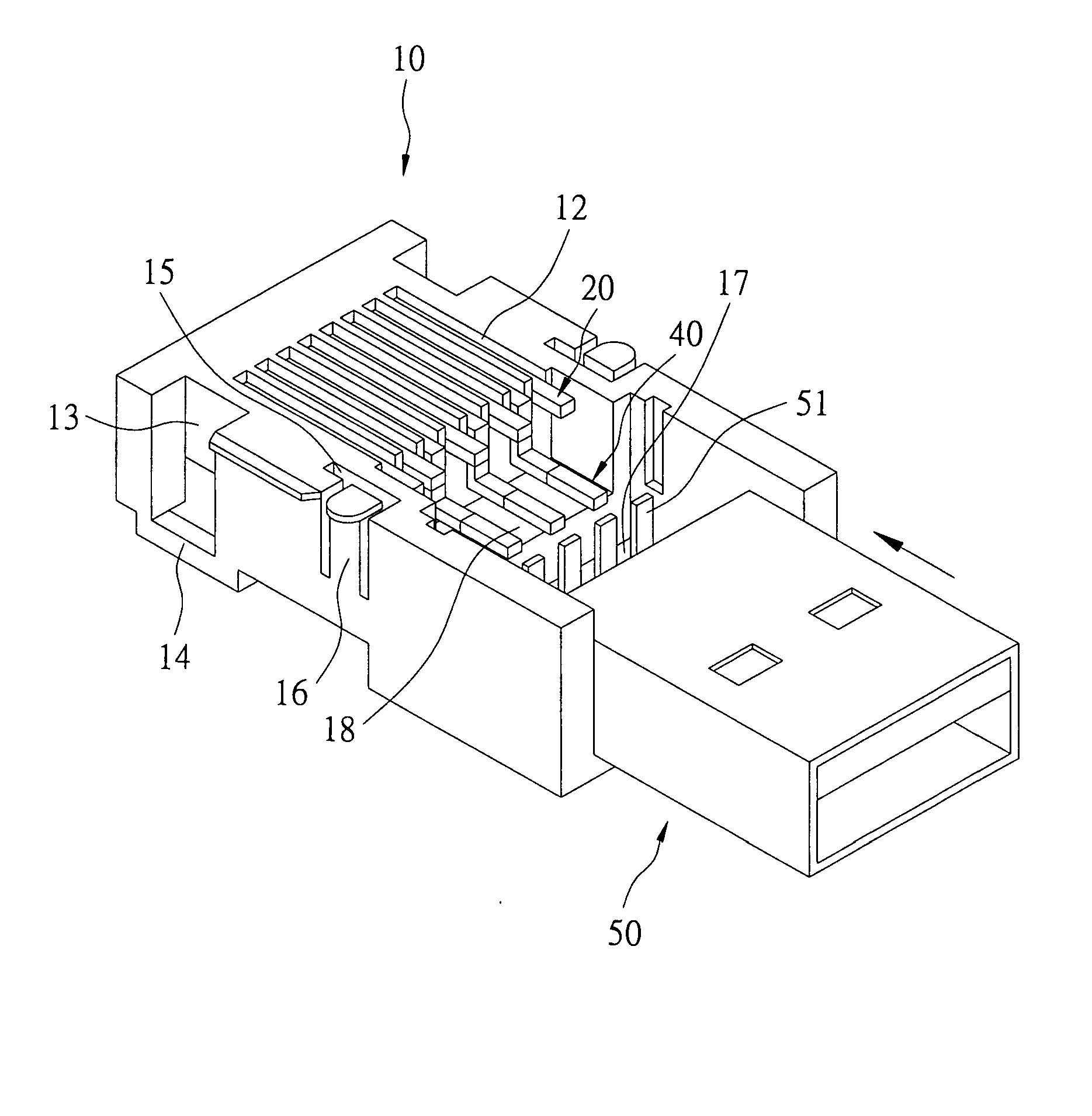
[0028] The carrying part 17 can link and join with a variety of linkers 50. As shown in FIG. 5, which shows an assembly view of the linking element connecting and joining with the linker 50 of the present invention. The linker 50 can be a USB or a Mini USB. There are a plurality of pins 51 at the rear side of the linker 50. The pins 51 of the linker 50 are linked and joined with the linking element 40 via a welding method to make the linker 50 electrically connect with the pins 20. After the linker 50 electrically connects with the pins 20, an insulating layer 19 (as shown in FIG. 7) is covered. The insulating layer 19 covers the pins 51 of the linker 50 and the linking element 40 to protect the linker 50 and the linking element 40. The insulating layer 19 is made of plastic or rubber. Alternatively, after the linker 50 links and joins with the linking element 40, a carrying part shell cover 30′ is movably wedged. The insulting main body 10 wedges with the carrying part shell cover ...

second embodiment

[0029] Please refer to FIG. 8, which shows an assembly perspective view of the present invention linking with the linker 60. The linker 60 is a DC plug. After the linker 60 links and joins with the carrying part 17 to achieve the electrical connection, an insulating layer 19 is covered to protect the linker 60 and the linking element 40 located in the insulating main body 10 (not shown in the figure). Alternatively, the insulting main body 10 wedges with the carrying part shell cover 30′ to achieve the same function (not shown in the figure).

third embodiment

[0030] Please refer to FIG. 9, which shows an assembly perspective view of the present invention linking with the linker 70. The linker 70 is an IEEE 1394 plug. After the linker 70 links and joins with the carrying part 17 to achieve the electrical connection, an insulating layer 19 is covered to protect the linker 70 and the linking element 40 located in the insulating main body 10 (not shown in the figure). Alternatively, the insulting main body 10 wedges with the carrying part shell cover 30′ to achieve the same function (not shown in the figure).

[0031] Please refer to FIG. 10. The first extended flakes 100 and the second extended flakes 160 are used for wedging movably the insulating main body 10 with a line-wrapped disk 82. On the proper location of the surface of the line-wrapped disk 82, there are two wedging parts 83 that correspond to each other. The first extended flakes 100 and the second extended flakes 160 are slidably wedged in the wedging part 83 to make the insulatin...


PUM


Abstract

A mobile transforming plug includes an insulating main body, a shell cover, a linking element and a linker. At the front side of the insulating main body, a connecting part is formed. A carrying part is formed at the rear side of the insulating main body. There is a connection area on the carrying part. The front two sides of the insulating main body each have a concave slot and a wedging-buckling end. A wedge extends from each of the two sides of the shell cover. The wedges are positioned in the concave slots and are wedged movably at the wedging-buckling end. The linking element is located at the connection area and connected with the pins. The linker is linked with the linking element. Thereby, the plug is plugged movably with the Internet or telephone plug. It can be plugged movably with the external plughole of electronic information products.

Description

BACKGROUND OF THE INVENTION [0001] 1. Field of the Invention [0002] The present invention relates to a plug. In particular, this invention relates to a mobile transforming plug that can link with an Internet plug and be plugged into an electronic information product. [0003] 2. Description of the Related Art [0004] Taiwan patent TW374512 discloses a mobile telephone line connection base. The prior art includes a base and an upper cover. There are a plurality of metal conducting lines that pass through the front and back ends of the base. At the side surface of the base, there is a buckling-joining hole. The upper cover is wedged movably with the base. A fastener extends from each of the two sides of the upper cover. The fastener can be plugged in to the base, and buckled and joined with the buckling-joining hole. The fastener can move upward and downward within the buckling-joining hole. Thereby, the front side and the back side of the base can individually and movably plug with a te...

Claims


Application Information

Patent Timeline
IPC IPC(8): H01L27/12
CPCH01R31/005H01R24/62H01R31/06
Inventor LIAO, SHENG-HSIN
Owner LIAO SHENG HSIN
Why Eureka
Try Eureka