Light source device, display device, terminal device, and transparent/scattering state switching element

a technology of switching element and display device, which is applied in the direction of optics, optical light guides, instruments, etc., can solve the problems of insignificant grayscale inversion, poor contrast and other aspects of display performance compared to transmisive type, and inability to improve visual characteristics, etc., and achieve the effect of changing color

Active Publication Date: 2007-11-22
BEIHAI HKC OPTOELECTRONICS TECH CO LTD
View PDF4 Cites 73 Cited by
  • Summary
  • Abstract
  • Description
  • Claims
  • Application Information

AI Technical Summary

Benefits of technology

[0070] In accordance with the present invention, a change in color can be prevented from occurring during switching of the radiation angle in a light source dev

Problems solved by technology

Energy consumption can be reduced in the reflective type, since external light can be utilized in the display device, but contrast and other aspects of display performance are inferior compared to the transmissive type.
This problem of grayscale inversion was relatively insignificant in mobile telephones and other terminal devices when the display content consisted mainly of telephone numbers and other characters.
The visual characteristics do not improve in this case, and the viewing angle characteristics resemble those of a conventional TN liquid crystal, but only a user who is positioned in front of the display can correctly see the image.
As a resu

Method used


Image

  • Light source device, display device, terminal device, and transparent/scattering state switching element
  • Light source device, display device, terminal device, and transparent/scattering state switching element
  • Light source device, display device, terminal device, and transparent/scattering state switching element

Examples


first embodiment

[0112] As shown in FIG. 4, the display device 2 is composed of a light source device 1 and a transmissive liquid crystal display panel 7. A light-guide plate 3 composed of a transparent material is provided in the light source device 1. The light-guide plate 3 is in the shape of a rectangular sheet. A light source is disposed in a position opposite one of the side surfaces (light-incident surface 3a) of the light-guide plate 3. The light source is a white LED (Light-Emitting Diode) 51, for example. A plurality of white LEDs 51 is arranged along the light-incident surface 3a of the light-guide plate 3, and the number of LEDs is five, for example. Light that enters the light-guide plate 3 from the light-incident surface 3a is evenly emitted from the principal surface (light-excident surface 3b) of the light-guide plate 3.

[0113] An optical film 4 is provided on the light-excident surface 3b side of the light-guide plate 3. The optical film 4 deflects the light emitted from the light-g...

second embodiment

[0152] the present invention will next be described. FIG. 10 is a perspective view showing the display device according to the present embodiment; and FIG. 11 is a sectional view showing the transparent / scattering state switching element that is a constituent element of the present embodiment.

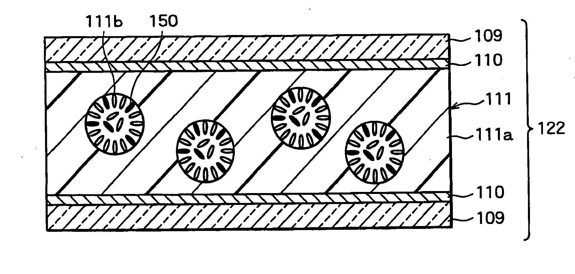
[0153] As shown in FIGS. 10 and 11, the display device 21 and the light source device 11 according to the second embodiment differ from the display device 2 and the light source device 1 of the previously described first embodiment in that a transparent / scattering state switching element 123 is used instead of the transparent / scattering state switching element 122, and blue dichroic dye molecules 151 are used instead of the blue dichroic dye molecules 150. The transparent / scattering state switching element 123 has a PDLC layer 113. Since the aforementioned blue dichroic dye molecules 150 were a dichroic dye that is more soluble in the liquid crystal material than in the photocuring resin, the b...

third embodiment

[0155] the present invention will next be described. FIG. 12 is a perspective view showing the display device according to the present embodiment; FIG. 13 is a sectional view showing the transparent / scattering state switching element that is a constituent element of the present embodiment; FIG. 14 is a plan view showing the transparent / scattering state switching element; FIG. 15 is a sectional view showing the orientation state of the liquid crystal molecules and the blue dichroic dye molecules when the transparent / scattering state switching element of the present embodiment is in the scattering state; and FIG. 16 is a sectional view showing the orientation state of the liquid crystal molecules and the blue dichroic dye molecules when the transparent / scattering state switching element is in the transparent state.

[0156] As shown in FIG. 12, the display device 22 and the light source device 12 of the third embodiment differ from the display device 2 and the light source device 1 of th...


PUM

PropertyMeasurementUnit
Coloraaaaaaaaaa
Dielectric anisotropyaaaaaaaaaa
Transparencyaaaaaaaaaa

Abstract

A light source device has a transparent/scattering state switching element for switching the range of irradiation angles, and liquid crystal molecules and dichroic dye molecules are dispersed in a polymer matrix in the PDLC layer of the transparent/scattering state switching element. The range of irradiation angles can thereby be switched, and the color can be prevented from changing when the radiation angle is switched.

Description

BACKGROUND OF THE INVENTION [0001] 1. Field of the Invention [0002] The present invention relates to a light source device capable of switching the radiation angle of illuminating light, to a display device provided with this light source device and capable of switching the angle range of visibility, to a terminal device equipped with this display device, and to a transparent / scattering state switching element built into the light source device. [0003] 2. Description of the Related Art [0004] Because of their thin profile, light weight, small size, low energy consumption, and other advantages, display devices that use liquid crystals have been widely deployed and used in a range of devices that includes monitors, televisions (TV: Television), and other large terminal devices; notebook-type personal computers, cash dispensers, vending machines, and other mid-sized terminal devices; and personal TVs, PDAs (Personal Digital Assistance: personal information terminal), mobile telephones,...

Claims


Application Information

Patent Timeline
IPC IPC(8): G02F1/1335G02F1/1333
CPCG02B6/0016G02B6/0038G02B6/0053G02B6/0068G02B6/0073G02F2203/03G02F1/13725G02F2001/13775G02F2202/04G02F2202/046G02F1/1323G02F1/13775
Inventor UEHARA, SHIN-ICHI
Owner BEIHAI HKC OPTOELECTRONICS TECH CO LTD
Why Eureka
Try Eureka