Noise reducing combustor

a combustor and noise reduction technology, applied in the direction of hot gas positive displacement engine plants, combustion processes, lighting and heating apparatus, etc., can solve the problems of reducing the noise generated by combustors incorporating helmholtz resonators, few have enabled the reduction of noise, and the noise produced by gas turbine engines is largely caused. to achieve the effect of enabling noise reduction

Active Publication Date: 2007-11-29
PRATT & WHITNEY CANADA CORP
View PDF29 Cites 40 Cited by
  • Summary
  • Abstract
  • Description
  • Claims
  • Application Information

AI Technical Summary

Benefits of technology

[0008]In another aspect, the present invention provides a method of reducing noise emissions of a gas turbine engine, the method comprising introducing an effusion airflow from a compressor section of the engine through a wall of a combustor of the engine, and directing the effusion airflow along a direction extending at a first angle with respect to a surface of the wall and at a second angle with respect to a radial plane extending radially from a central axis of the combustor to produce a time delay between a noise generated in the compressor section and at least one of a noise generated in the combustor and a noise amplified in the combustor.
[0009]In a further aspect, the present invention provides a method of manufacturing a combustor for reducing noise emissions in a gas turbine engine, the method comprising selecting a first effusion hole density for a primary combustion section of the combustor according to a desired frequency range of the noise emissions to be attenuated, selecting a second effusion hole density for a remaining section of the combustor, the second density being smaller than the first density, and defining effusion holes through walls of the combustor following hole directions angled with respect to a corresponding one of the walls and to a respective radial plane extending radially from a central axis of the combustor, the effusion holes being defined in the primary section according to the first density and in the remaining section according to the second density.

Problems solved by technology

Noise produced by gas turbine engines is largely caused by pressure and acoustic vibrations which can occur in and around the combustion chamber under certain conditions.
However, few have enabled the reduction of noise generated by the combustion chamber of such a gas turbine engine.
However, combustors incorporating Helmholtz resonators are generally complex to manufacture.
In addition, the double wall construction generally renders the combustor more complex and costly to manufacture.

Method used


Image

  • Noise reducing combustor
  • Noise reducing combustor
  • Noise reducing combustor

Examples


Embodiment Construction

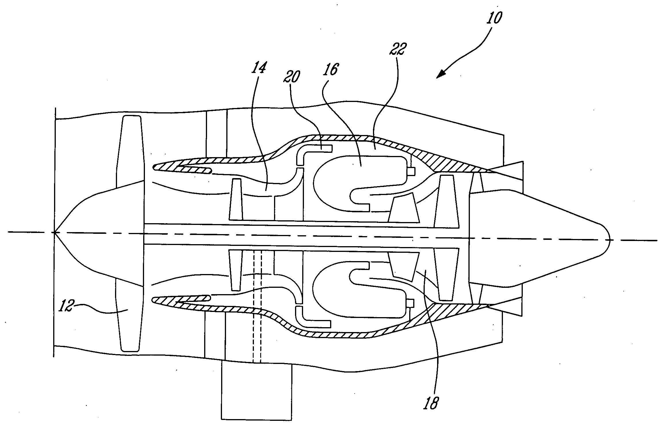
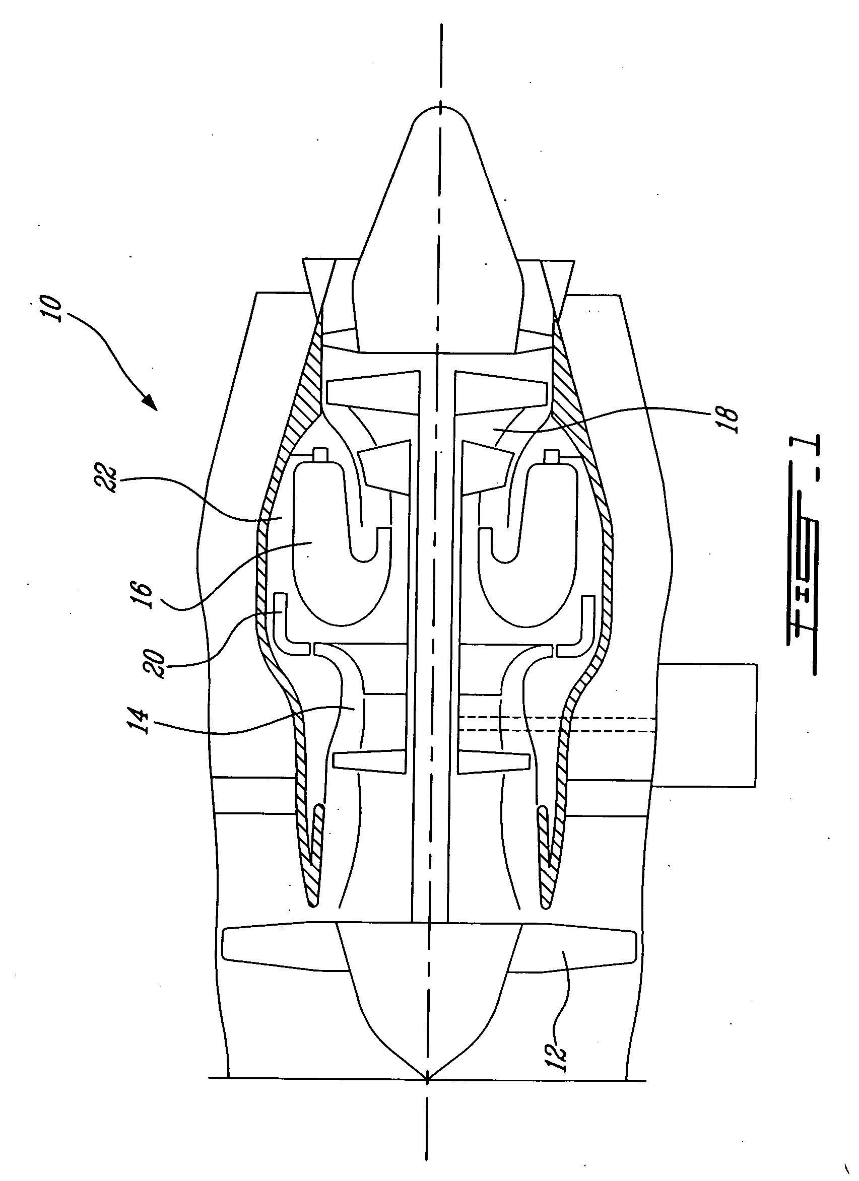
[0017]FIG. 1 illustrates a gas turbine engine 10 of a type preferably provided for use in subsonic flight, generally comprising in serial flow communication a fan 12 through which ambient air is propelled, a multistage compressor 14 for pressurizing the air, a combustor 16 in which the compressed air is mixed with fuel and ignited for generating an annular stream of hot combustion gases, and a turbine section 18 for extracting energy from the combustion gases.

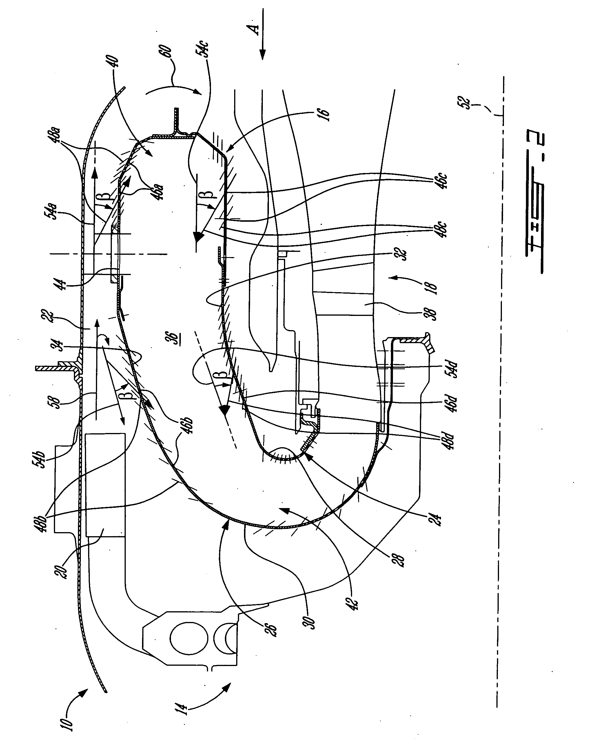
[0018]Referring to FIG. 2, the air exiting the compressor 14 passes through a diffuser 20 and enters a gas generator case 22 which surrounds the combustor 16. The combustor 16 includes interconnected inner and outer annular walls or liners 24, 26 which receive the airflow circulating in the gas generator case on outer surfaces 28, 30 thereof, and which define an annular enclosure or combustion chamber 36 between inner surfaces 32, 34 thereof. The annular stream of hot combustion gases travels through the combustion chamber 36 a...


PUM


Abstract

A combustor having liners with a plurality of angled effusion holes defined therethrough at a first angle with respect to a surface of the liners and at a second angle with respect to a corresponding radial plane. A density of the effusion holes defined in a primary section receiving the fuel nozzles is at least equal to a density of the effusion holes defined in a secondary downstream section.

Description

TECHNICAL FIELD[0001]The invention relates generally to gas turbine engines and, more particularly, to an improved combustor for such engines providing low noise levels.BACKGROUND OF THE ART[0002]Noise produced by gas turbine engines is largely caused by pressure and acoustic vibrations which can occur in and around the combustion chamber under certain conditions. Many advancements have been made to reduce the overall noise levels generated by gas turbine engines. However, few have enabled the reduction of noise generated by the combustion chamber of such a gas turbine engine.[0003]In some cases, the noise of the combustion chamber is damped by providing Helmholtz resonators as damping elements to eliminate undesirable vibrations, which contribute to noise levels. However, combustors incorporating Helmholtz resonators are generally complex to manufacture.[0004]In other cases, the combustors have a double wall construction, i.e. interconnected inner walls defining the combustion cham...

Claims


Application Information

Patent Timeline
Patent Type & Authority Applications(United States)
IPC IPC(8): F02C1/00
CPCF23R3/06F23R2900/03041F23R3/54F23R3/50
Inventor ALKABIE, HISHAM
Owner PRATT & WHITNEY CANADA CORP
Why Eureka
Try Eureka