Method and Device for Fastening a Rivet Nut on a Workpiece

Inactive Publication Date: 2007-11-29
DAIMLER AG
View PDF3 Cites 1 Cited by
  • Summary
  • Abstract
  • Description
  • Claims
  • Application Information

AI Technical Summary

Benefits of technology

[0009] By virtue of the arrangement and design of a discharge channel in the follow-on tool in which the rivet nut is introduced into the hole produced in the preceding workstation, and as a result of the diameter of the discharge channel being at least as large as the maximum diameter of the rivet nut, unwelcome damage to the tools of the device according to the invention is prevented. If, for example following the consumption of the sheet metal panel material, another rivet nut is deposited at the location at which the first follow-on tool normally introduces the rivet nut into the punched hole, the rivet nut drops into the discharge channel, from which it is removed from the contact region of the tools of the device according to the invention. This means that when new sheet metal panel material is charged, the first follow-on tool downstream of the punching device can insert a rivet nut into the hole produced without being impeded. In the other case described above, in which the worker interrupts the operation and the transfer of the sheet metal panel is interrupted, with the inserted rivet nut remaining at the point of introduction in the tool, when the worker resumes the operation with a newly fed-in rivet nut, the first follow-on tool presses the already inserted rivet nut through the hole, causing it to drop into the discharge channel and consequently likewise to be withdrawn from the contact region of the tools of the device. Although the hole is damaged by the first rivet nut being pressed through it, making the sheet metal panel a reject, the tools, i.e. the first follow-on tool and the second follow-on tool, which is designed as a riveting tool, remain unimpaired. Overall, it is made possible for rivet nuts to be fastened on the workpiece, which is represented by the sheet metal panel, in a simple and problem-free manner since the risk of damage to the tools of the device according to the invention is precluded from the outset, resulting in no downtimes for repair purposes or replacement of the damaged tools.
[0010] In a particularly preferred development of the invention, the rivet nut in the first follow-on tool is pressed into the hole by the section to be riveted using a punch according to the development of the device according to the invention. This ensures that the rivet nut is provisionally secured to the workpiece, that is to say the sheet metal panel, so that when the workpiece is transferred to the riveting device, that is to say the second follow-on tool, the rivet nut does not get lost and can at the same time be fed with positional accuracy to the riveting tool, thereby guaranteeing tolerance-free riveting at the desired point on the workpiece. It is precisely during the pressing-in operation that the invention proves to be particularly advantageous since it is here that particularly high forces are applied which result in particularly sustained damage to the tool in the event of problems arising during conventional fastening of the rivet nut.
[0012] According to a particularly preferred development of the method according to the invention and of the device according to the invention, the stamping operation, as the first operation for fastening the rivet nut, is carried out in the same tool as the subsequent hole-punching operation. Here, the stamping tool and the punching tool are arranged jointly in a combination tool. This considerably minimizes the production tolerance for the relative position of the hole in the bead. Furthermore, integrating two processing steps in one tool is not only very economical in terms of the method but also provides a saving in terms of space requirement.

Problems solved by technology

This considerably minimizes the production tolerance for the relative position of the hole in the bead.

Method used


Image

  • Method and Device for Fastening a Rivet Nut on a Workpiece
  • Method and Device for Fastening a Rivet Nut on a Workpiece
  • Method and Device for Fastening a Rivet Nut on a Workpiece

Examples


Embodiment Construction

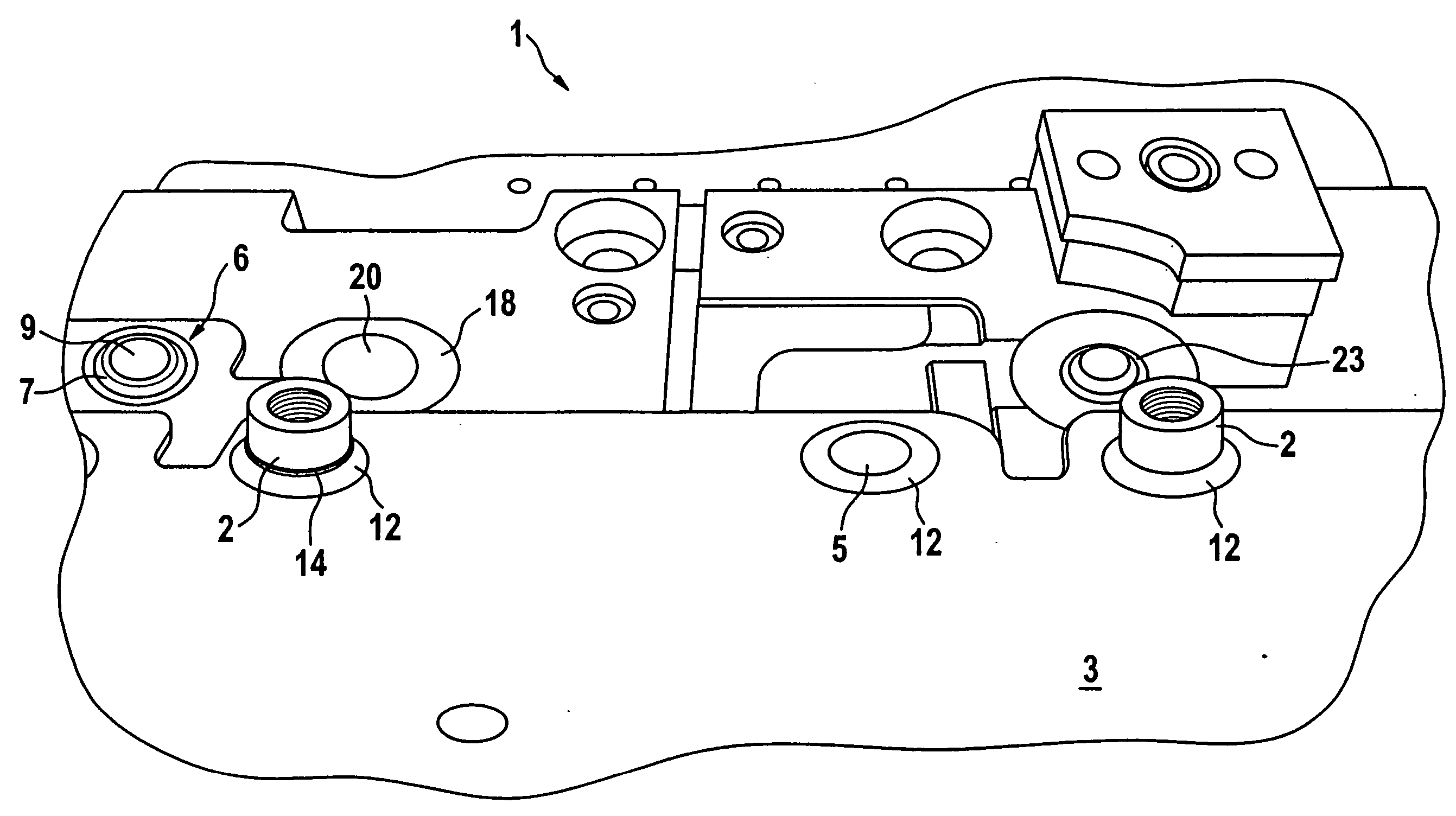
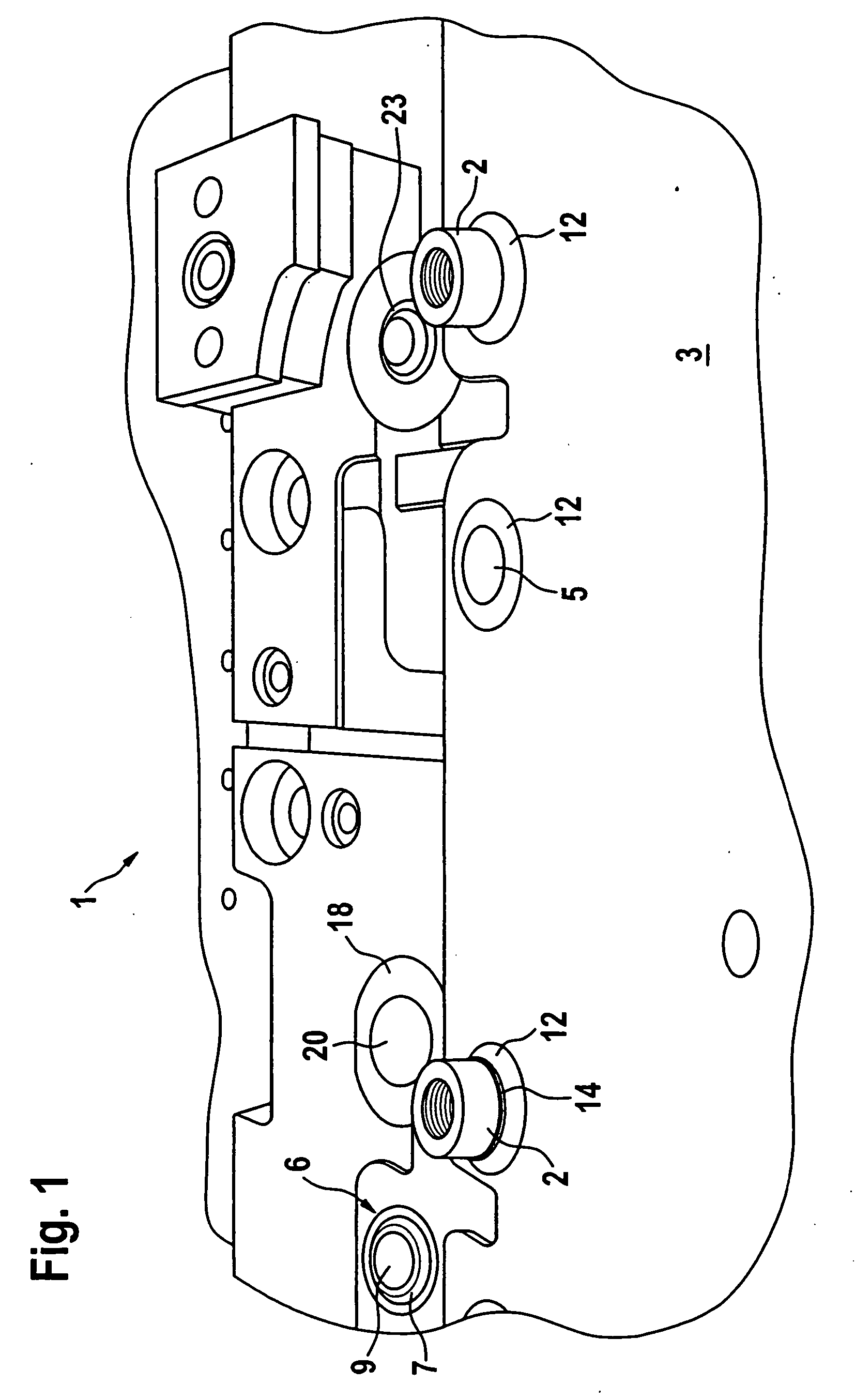
[0018]FIG. 1 represents a device 1 for fastening a rivet nut 2 on a workpiece 3, the device 1 being designed as a composite follow-on and progressive-transfer tool. The device 1 comprises a punching tool 4, as can be seen from FIG. 3, which is used to punch a hole 5 into the workpiece 3. The device 1 further includes a stamping tool 6, which is represented in FIG. 1 only by way of its bottom die, this die comprising a raised annular shape 7. The stamping tool 6 is used to carry out the first operation in the method sequence, i.e. stamping a boss-like bead 8 on the workpiece 3, which is formed by a sheet metal panel. The workpiece 3 then remains in the station of the stamping tool 6, since the bead 8 is subjected to punching at the same location by means of the punching tool 4, which is arranged jointly and coaxially with the stamping tool 6 in a combination tool, thereby forming the hole 5. For this purpose, the annular shape 7 of the stamping tool 6 has an opening 9 which is enclos...


PUM


Abstract

The invention relates to a method and a device for fastening a rivet nut (2) on a workpiece (3), in which a hole (5) is punched into this workpiece and the rivet nut (2) is introduced into this hole by its section (14) to be riveted, after which the rivet nut (2) is riveted to the workpiece (3) by means of a riveting tool. To make it possible for the rivet nut (2) to be fastened on a workpiece (3) in a simple and problem-free manner, it is proposed that, after the hole (5) has been punched, the workpiece (3) is fed to a first follow-on tool (13) in which the rivet nut (2) is introduced into the hole (5) by its section (14) to be riveted, the rivet nut (2) in the follow-on tool (13) being aligned with a discharge channel (19) which is arranged in the first follow-on tool (13) below the workpiece (3) and whose diameter is at least as large as the maximum diameter of the rivet nut (2). The rivet nut (2) now inserted in the hole (5) is then riveted in a second follow-on tool (21) designed as a riveting tool.

Description

CROSS-REFERENCE TO RELATED APPLICATION [0001] This application is a national stage of PCT / EP2005 / 000418 filed Jan. 18, 2005 and based upon DE 10 2004 004 384.1 filed on Jan. 29, 2004 under the International Convention BACKGROUND OF THE INVENTION [0002] 1. Field of the Invention [0003] The invention relates to a method for fastening a rivet nut on a workpiece and to a device. [0004] A generic method and a generic device are known from DE 101 17 060 A1. In this document, as shown by FIGS. 5a to f, a bead is stamped into a sheet metal panel and this bead is then perforated in the same tool by feeding in a punching rivet nut. Furthermore, the rivet nut, likewise in the same tool, is fitted into the punched hole by its section to be riveted, after which the sheet metal panel and nut are transferred to a follow-on tool in which the punched nut is riveted to the sheet metal panel as a result of the hole edge being enclosed by means of the rivet nut section to be riveted. Interruptions occu...

Claims


Application Information

Patent Timeline
IPC IPC(8): B23P19/06F16B37/06
CPCB23P19/062
Inventor ROTHERMUND, VOLKERWOICZIK, MARTIN
Owner DAIMLER AG
Why Eureka
Try Eureka