Crimp press apparatus

a crimp press and apparatus technology, applied in forging presses, forging/pressing/hammering apparatuses, manufacturing tools, etc., can solve the problems of plant shutdown and partially dismantling, and the crimp press idles for a longer time, so as to achieve minimum downtime, no downtime, and the effect of substantial increase in the productivity of the crimp press

Inactive Publication Date: 2005-11-08
KOMAX HOLDING
View PDF7 Cites 11 Cited by
  • Summary
  • Abstract
  • Description
  • Claims
  • Application Information

AI Technical Summary

Benefits of technology

[0008]The crimp press according to the present invention solves the objective of avoiding the disadvantages of the well-known installations and provides an installation by which, during the transition of different crimping contacts, no downtimes arise due to the conversion of the crimp press.
[0009]The advantages achieved by the crimp press according to the present invention are essentially that when processing different crimping contacts, the crimp devices and the taped crimping contacts may be mounted beforehand. The conversions are carried out outside the crimp press. The productivity of the crimp press can be substantially increased thereby, in particular, when small quantities of the same crimping contacts are processed. The installation, according to the present invention, allows handling with minimum downtimes several different types of contacts successively. This allows rapidly changing to a new type of contact, once a large quantity of one and the same type of contact is terminated.

Problems solved by technology

It is a disadvantage of this well-known installation that the crimp press lies idle for a longer time, due to the necessity of device change when processing different crimping contacts.
It is a disadvantage of this installation that with the change of contact rollers or crimping devices, the plant must be stopped and partially dismantled.

Method used


Image

  • Crimp press apparatus
  • Crimp press apparatus
  • Crimp press apparatus

Examples


Embodiment Construction

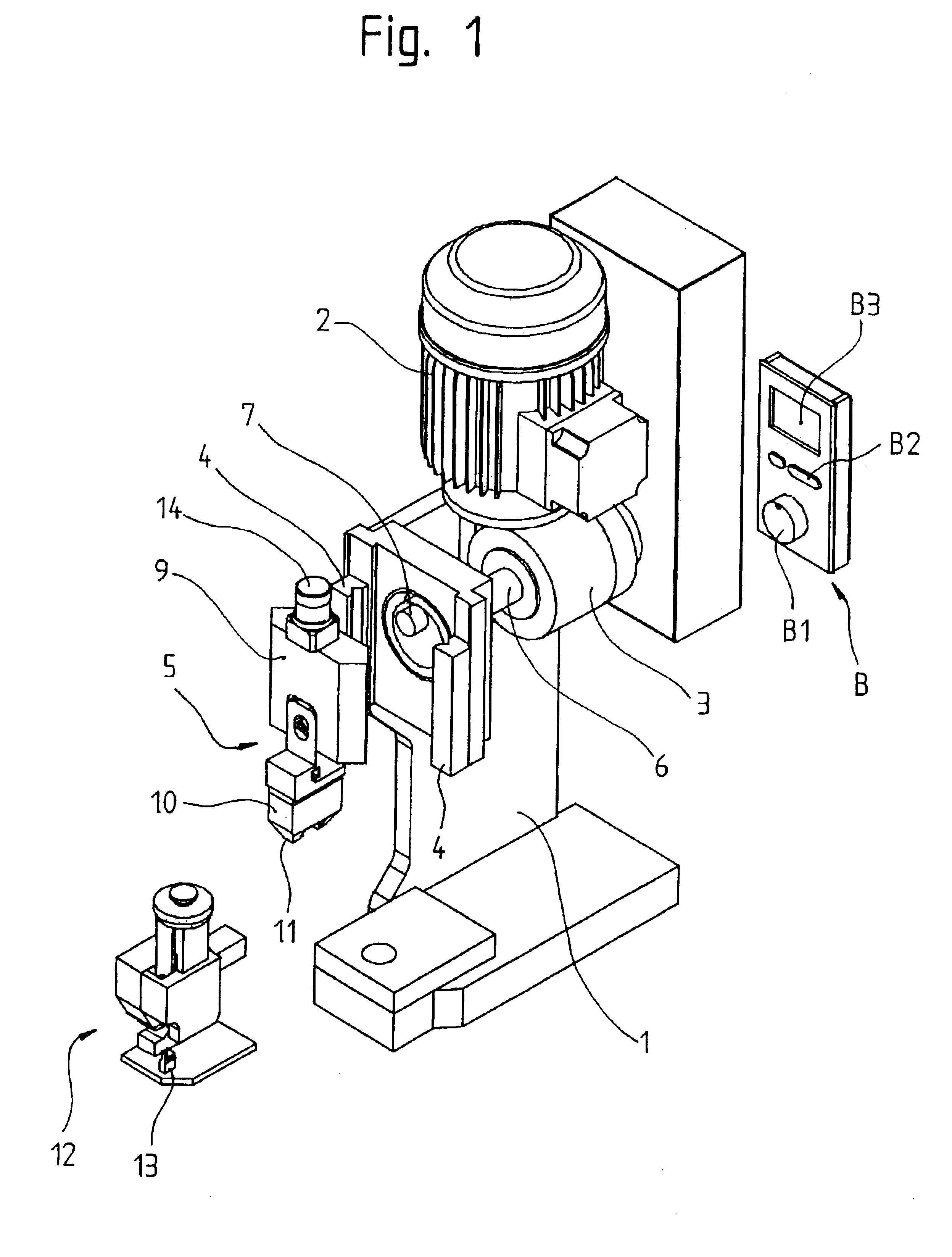
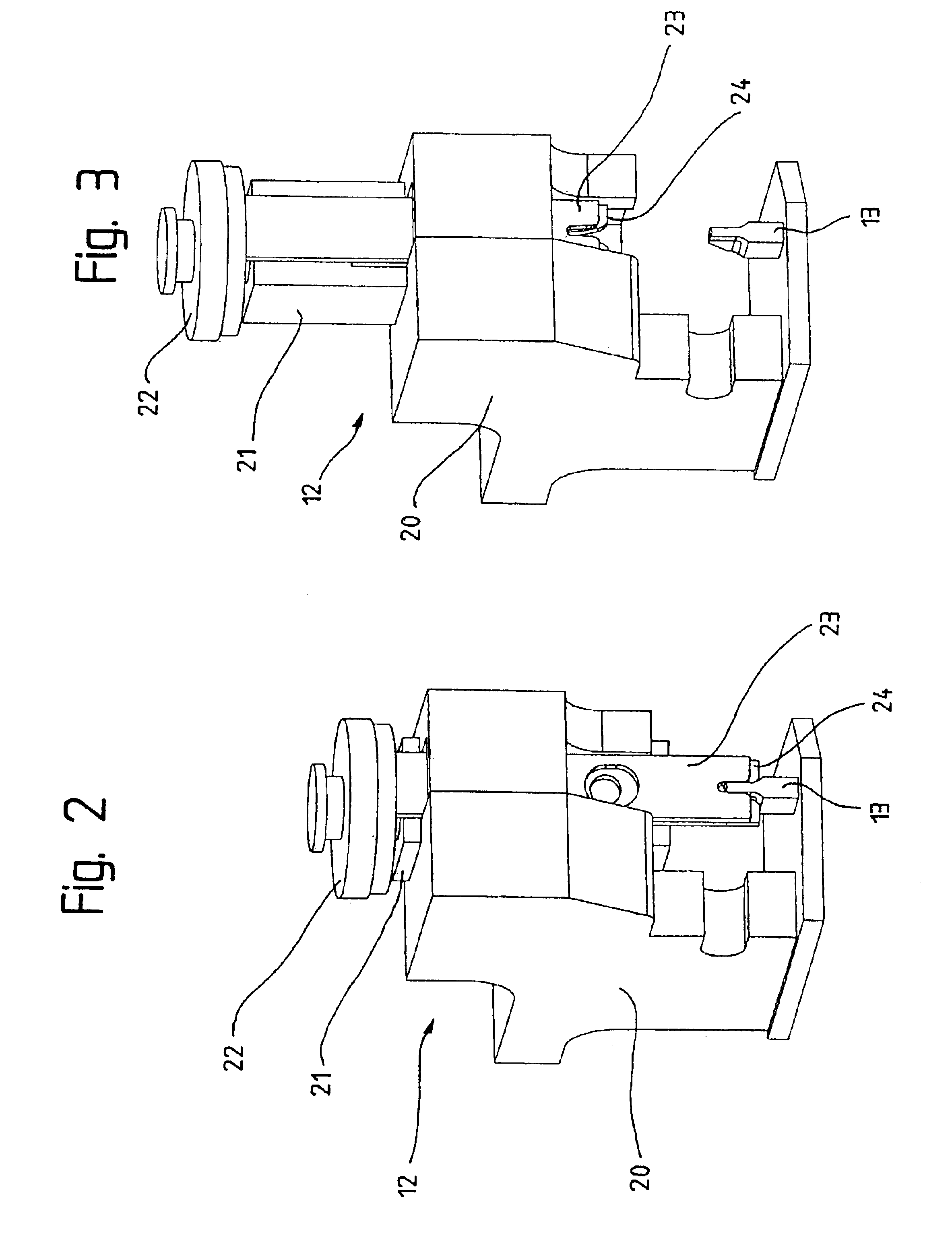
[0018]A crimp press is shown in FIG. 1 having a stand 1 with a right side panel removed, on which an engine 2 is arranged and a gearing 3, mounted on the stand 1, is arranged. In addition, first guides 4 are arranged on the stand 1 along which a crimping ram 5 is vertically guided. A shaft 6, driven by the gearing 3, has an eccentric pin 7 at a free end. The crimping ram 5 includes a carriage 9 guided by the first guides 4 and an attached tool holder 10 with a fork arm 11. The carriage 9 stands in a loose connection with the eccentric pin 7, whereby the rotation of the eccentric pin 7 is converted into a linear vertical up and down movement of the carriage 9. The maximum stroke of the carriage 9 is determined by an upper dead center position and a lower dead center position of the eccentric pin 7. The tool holder 10 operates a crimp device 12, which makes, together with an anvil 13 belonging to the device 12, the crimping connection. By means of an adjusting screw 14, the closing he...


PUM

PropertyMeasurementUnit
areaaaaaaaaaaa
height sensoraaaaaaaaaa
timeaaaaaaaaaa

Abstract

A crimp press apparatus with first and second crimping stations includes at each station a device platform with device stations and a crimp press. A cable is advanced by a tape drive whereby the leading cable end is supplied to the first crimping station. After the leading cable end is provided with a crimping contact, the tape drive continues to advance the cable until the desired length of a cable section is reached. A separation and a stripping station separates the cable section from the cable and removes the insulation at the cable ends. The lagging cable end of the cable section is supplied to the second crimping station for assembly with a crimping contact. With the device stations located on a rotatable disk, a change of a type of contact to another type of contact is possible with minimum downtime of the crimp press apparatus.

Description

BACKGROUND OF THE INVENTION[0001]The present invention relates to a crimp press for the production of a crimping connection by means of a driven crimping device, which device connects an end of a conductor of a cable with a crimping contact.[0002]An installation for the production of a crimping connection is shown in the U.S. Pat. No. 5,966.806. An engine drives an eccentric shaft, which moves up and down a carriage with crimping devices. An encoder, driven by the motor shaft, serves for the indication of the position of the crimping device. The crimping contact, which is to be connected with an end of a conductor, lies on a fixed anvil, whereby the tabs of the crimping contact are plastic deformed by the downward movement of the crimping device and provide the connection to the conductor. The position of the crimping device within the crimping area is measured by means of a height sensor, whereby the sensor signal is employed independently from the encoder signal.[0003]It is a disa...

Claims


Application Information

Patent Timeline
Patent Type & Authority Patents(United States)
IPC IPC(8): H01R43/048H01R43/04
CPCH01R43/048Y10T29/53213Y10T29/53387Y10T29/53226Y10T29/53235Y10T29/49185Y10T29/53243Y10T29/5193Y10T29/53217Y10T29/53087Y10T29/53383Y10T29/53261Y10T29/53365Y10T29/53039
Inventor CONTE, ALOIS
Owner KOMAX HOLDING
Why Eureka
Try Eureka