Method of riser deployment on a subsea wellhead

a wellhead and riser technology, applied in the direction of drilling rods, drilling casings, drilling pipes, etc., can solve the problems of time-consuming repositioning of floating rigs, inherent unpredictability of tidal forces both in strength and direction, and achieve the effect of reducing or eliminating the effect of wave action and less effor

Inactive Publication Date: 2007-11-29
BAKER HUGHES INC
View PDF36 Cites 11 Cited by
  • Summary
  • Abstract
  • Description
  • Claims
  • Application Information

AI Technical Summary

Benefits of technology

[0004]The riser assembly is plugged adjacent its bottom end either as it is made up or after full makeup or anywhere in between. A heavy fluid is either added to the riser string as it is made up or delivered into the string after makeup to displace seawater or other fluids that may have been in the riser as it is assembled. The floating rig can be secured over the subsea well head and the riser now full of heavy fluid is less prone to be displaced by wave action and preferably simply dangles straight down so that the connection to the subsea wellhead can be simply accomplished. The effect of wave action is minimized or eliminated when deciding placement of the floating rig with respect to the wellhead. Repositioning of the rig takes less effort and is needed less frequently.

Problems solved by technology

The problem lies in the inherent unpredictability of the tidal forces both in strength and in direction.
Repositioning of the floating rig is time consuming and may require the riser string to be pulled back onto the rig before it can be repositioned.

Method used


Image

  • Method of riser deployment on a subsea wellhead
  • Method of riser deployment on a subsea wellhead

Examples


Embodiment Construction

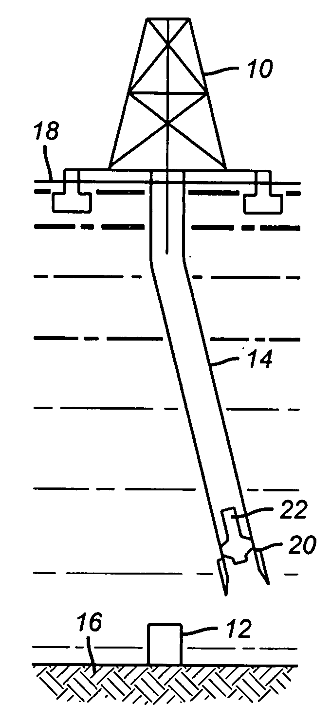
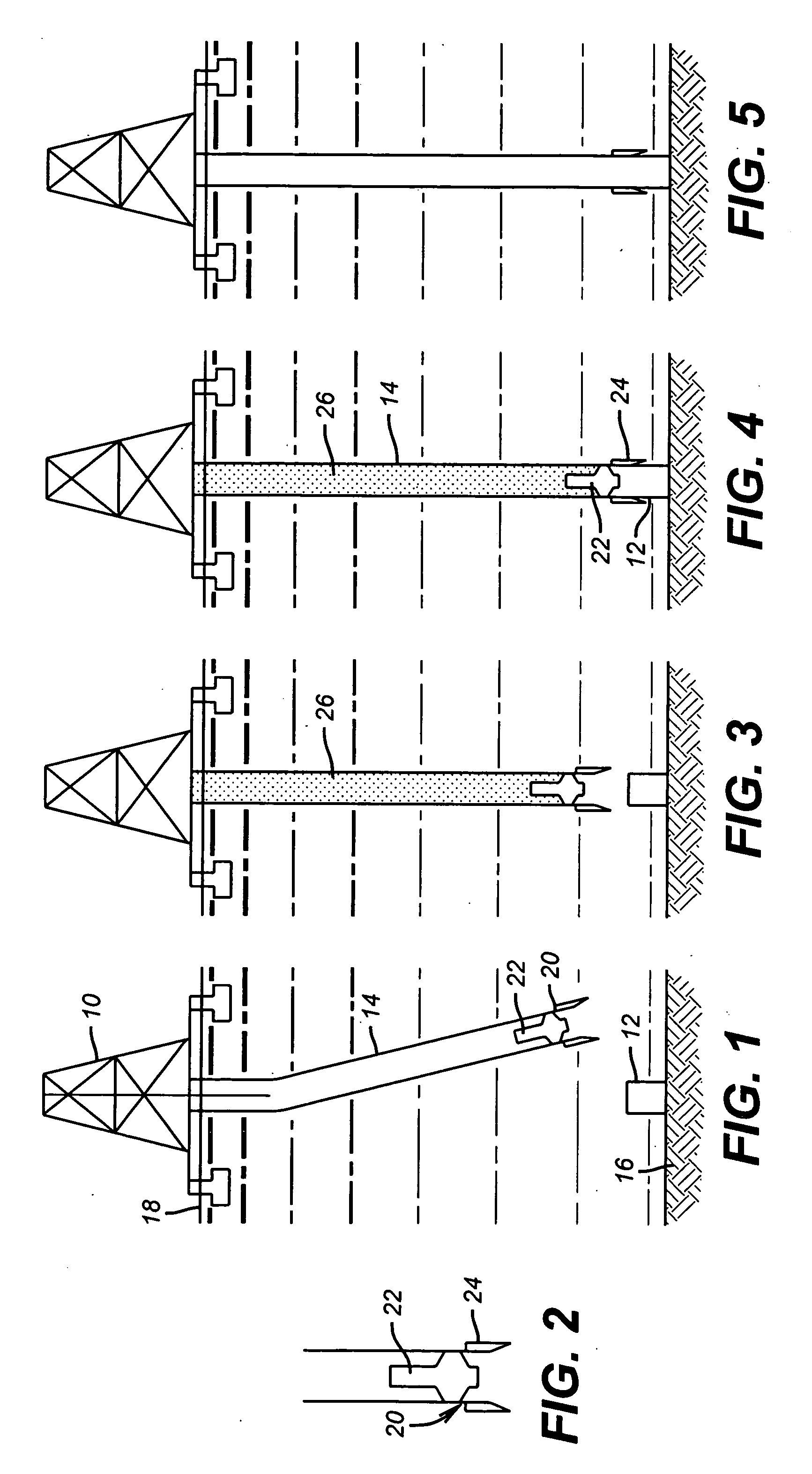
[0010]FIG. 1 shows a floating rig 10 set over a subsea wellhead 12 and supporting a riser 14 that is being deflected by currents active between the sea bed 16 and the surface 18. Near the lower end 20 of the riser 14 is a plug 22 that can be installed when the riser string 14 is assembled or later after it is fully assembled by running it in using a variety of known techniques. In the event the plug 22 is initially installed in the lowermost joint or joints of the riser string 14, drilling mud or seawater, for example, can be added above the plug 22 as each stand of riser pipe is connected at the surface and lowered in. FIG. 2 shows the lower end 20 closer up showing the plug 22 and schematically illustrating the connecting hardware 24 to attach to the wellhead 12. The plug can be deployed or dropped into the riser 14 and displaced with heavy fluid to a seat within the riser 14. Alternatively, the plug can be in position at the lower end of the riser but not seated off so as to allo...


PUM


Abstract

The riser assembly is plugged adjacent its bottom end either as it is made up or after full makeup or anywhere in between. A heavy fluid is either added to the riser string as it is made up or delivered into the string after makeup to displace seawater or other fluids that may have been in the riser as it is assembled. The floating rig can be secured over the subsea well head and the riser now full of heavy fluid is less prone to be displaced by wave action and preferably simply dangles straight down so that the connection to the subsea wellhead can be simply accomplished. The effect of wave action is minimized or eliminated when deciding placement of the floating rig with respect to the wellhead. Repositioning of the rig takes less effort and is needed less frequently.

Description

FIELD OF THE INVENTION[0001]The field of this invention is riser placement on a subsea wellhead and more specifically when using a floating rig.BACKGROUND OF THE INVENTION[0002]Floating rigs are connected to subsea wellheads through a string called a riser that spans the distance between the rig floor and the wellhead located just above the sea floor. Floating rigs are normally positioned and secured to hold a selected position while still able to compensate for the rise and fall of the surface from wave action. Before or after a rig is positioned the riser assembly is made up in sections on the rig floor and run in. If the riser is made up before, the currents can be used to guide the rig closer to the subsea BOP. The water depths for some floating rigs can be in the thousands of meters and the wave action at the surface has a component below the surface that can deflect the riser string as it is made up and lowered toward the wellhead. The skewing effect is well known and in the p...

Claims


Application Information

Patent Timeline
Patent Type & Authority Applications(United States)
IPC IPC(8): E21B17/01
CPCE21B17/01
Inventor PALMER, LARRY T.DOLYNIUK, DAVID
Owner BAKER HUGHES INC
Why Eureka
Try Eureka