Multi-Pane Window Assembly with Two-Sided Frame and Sliding Pane

a window assembly and multi-pane technology, applied in mechanical equipment, transportation and packaging, wing accessories, etc., can solve the problems of undetected bulkiness of the window assembly and poorly integrated into the exterior surface of the vehicle or other structure, and achieve the effect of reducing the effect of sink marks

Inactive Publication Date: 2012-06-07
PLASMAN US HOLDCO LLC
View PDF7 Cites 3 Cited by
  • Summary
  • Abstract
  • Description
  • Claims
  • Application Information

AI Technical Summary

Benefits of technology

[0007]An advantageous aspect of at least certain exemplary embodiments of the window assemblies disclosed here is their strength during the post-molded handling and customer operations, such as installation and support of the assemblies. Also, an advantageously flush and uniform appearance can be achieved. In certain exemplary embodiments, the elongate reinforcement member(s) are at least partly embedded in the substantially full circumference molded frame member and extend laterally above or below the window opening behind a “show surface,” i.e., a surface portion of the molded frame member which forms the aforesaid exterior surface of the assembly. Advantageously, such exterior surface of the assembly is flush with adjacent (non-recessed) surface of the window aperture. The reinforcement members in such embodiments provide not only structural reinforcement, but also help to eliminate and / or minimize the effects of sink marks and witness lines that would otherwise occur in such exterior surface.
[0008]In general, well-designed embodiments of the window assemblies disclosed here provide a desirable flush and smooth look from the exterior. Certain exemplary embodiments also provide additional advantageous features, including, e.g., a two-sided seal lip (a ‘D’-shaped or ‘v’-shaped lip, etc.) extending radially at the perimeter of the window assembly. The peripheral lip seal can provide a continuous seal surface without steps or offsets. Such lip seal provides, in at least certain embodiments, the following added benefits:1) a secondary seal to sheet metal for added water management protection;2) a more arduous path for noise transmission into the cabin area of a vehicle, thereby providing improved NVH, i.e., improved noise prevention performance; and3) masking or hiding of bonding material which might squeeze or migrate into an area otherwise viewable during installation of the window assembly in a recessed window aperture. This provides greater freedom and more packaging space for the bonded material. It can reduce or eliminate rejects for exposed bonding agent, which has been a problem experienced at assembly plants with so-called raw-edge-of-glass designs.4) Window assemblies in accordance with the present disclosure may be referred to as two-sided designs. Correspondingly, the substantially full-circumference, molded plastic frame member may be referred to as a two-sided frame member. This refers to a configuration of the frame around some or all of the otherwise raw edge of the fixed or stationary panes, especially the edge at their outboard peripheries. As further described below, the frame member is molded against a peripheral portion of the inside surface of the stationery pane and, in addition, against (at least a portion of) the peripheral edge surface of the pane. The exterior surface of the frame member preferably is flush with the adjacent surface of the fixed pane along this interface. Any variation in the dimension of the glass pane is compensated for by the frame member simply being molded to the raw edge. Thus, a gap-less, flush result is achieved irrespective of tolerance variations in the glass. It is a significant advantage of at least certain embodiments of the window assemblies disclosed here, that the 2-side molded plastic frame provides for this improved tolerance—compared to raw-edge-of glass designs—for inevitable variance in the precise dimensions of stationary glass panes. The 2-sided molded plastic frame also provides for an improved appearance between the stationary glass and the molded plastic frame in the slide glass area. Current products on the market have gaps or margins between the stationary glass edge and the appearance portion of the upper and lower frame areas. These gaps are required for assembled products due to component tolerances. This invention reduces or eliminates these gaps via the 2-sided molding feature, which provides for a gap-less appearance and, in at least certain embodiments, a flush appearance.

Problems solved by technology

In the past, windows assemblies have had an undesirably bulky appearance poorly integrated into the exterior surface of the vehicle or other structure.
1) a secondary seal to sheet metal for added water management protection;
2) a more arduous path for noise transmission into the cabin area of a vehicle, thereby providing improved NVH, i.e., improved noise prevention performance; and
3) masking or hiding of bonding material which might squeeze or migrate into an area otherwise viewable during installation of the window assembly in a recessed window aperture. This provides greater freedom and more packaging space for the bonded material. It can reduce or eliminate rejects for exposed bonding agent, which has been a problem experienced at assembly plants with so-called raw-edge-of-glass designs.
4) Window assemblies in accordance with the present disclosure may be referred to as two-sided designs. Correspondingly, the substantially full-circumference, molded plastic frame member may be referred to as a two-sided frame member. This refers to a configuration of the frame around some or all of the otherwise raw edge of the fixed or stationary panes, especially the edge at their outboard peripheries. As further described below, the frame member is molded against a peripheral portion of the inside surface of the stationery pane and, in addition, against (at least a portion of) the peripheral edge surface of the pane. The exterior surface of the frame member preferably is flush with the adjacent surface of the fixed pane along this interface. Any variation in the dimension of the glass pane is compensated for by the frame member simply being molded to the raw edge. Thus, a gap-less, flush result is achieved irrespective of tolerance variations in the glass. It is a significant advantage of at least certain embodiments of the window assemblies disclosed here, that the 2-side molded plastic frame provides for this improved tolerance—compared to raw-edge-of glass designs—for inevitable variance in the precise dimensions of stationary glass panes. The 2-sided molded plastic frame also provides for an improved appearance between the stationary glass and the molded plastic frame in the slide glass area. Current products on the market have gaps or margins between the stationary glass edge and the appearance portion of the upper and lower frame areas. These gaps are required for assembled products due to component tolerances. This invention reduces or eliminates these gaps via the 2-sided molding feature, which provides for a gap-less appearance and, in at least certain embodiments, a flush appearance.

Method used


Image

  • Multi-Pane Window Assembly with Two-Sided Frame and Sliding Pane
  • Multi-Pane Window Assembly with Two-Sided Frame and Sliding Pane
  • Multi-Pane Window Assembly with Two-Sided Frame and Sliding Pane

Examples


Embodiment Construction

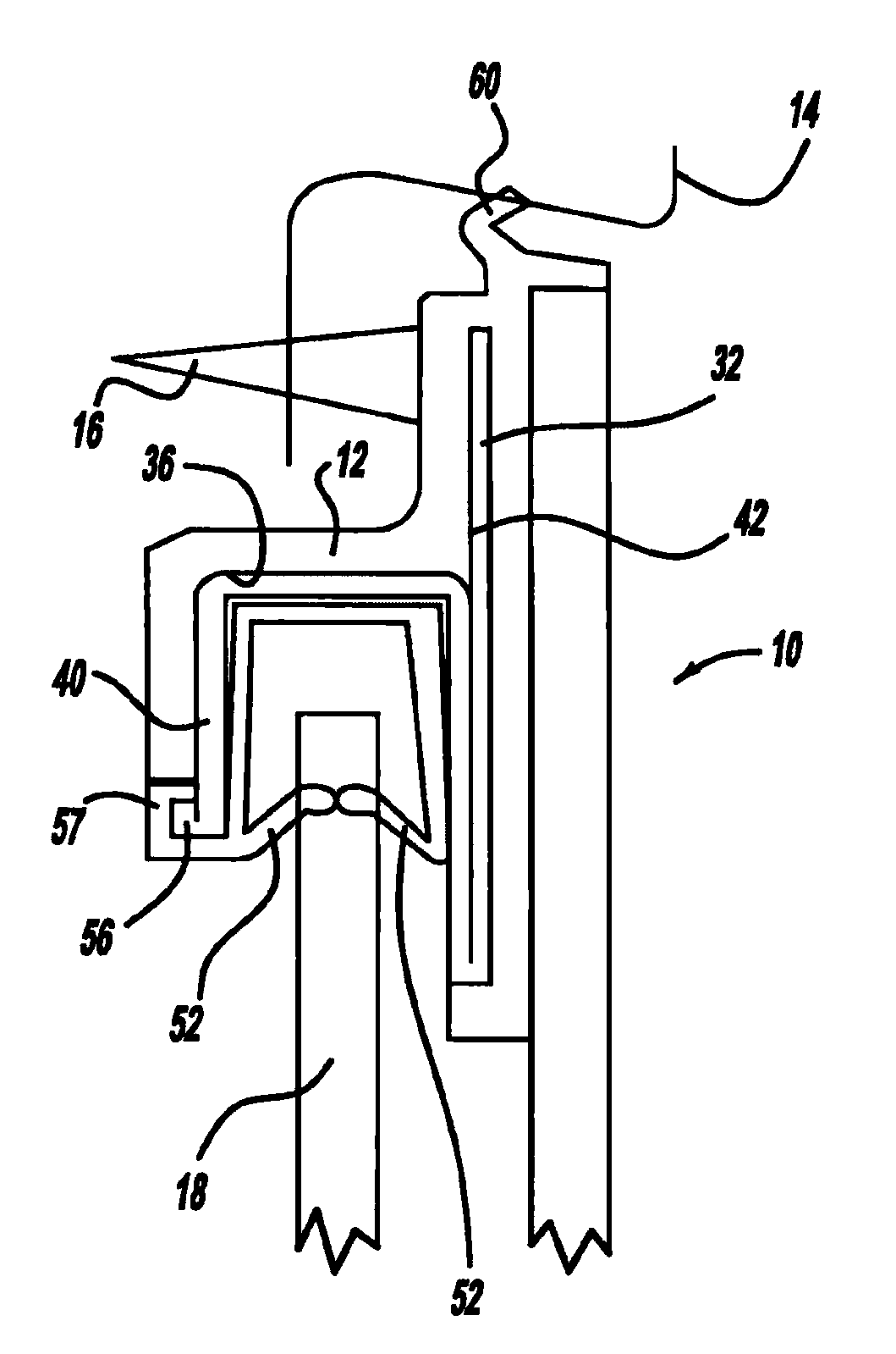
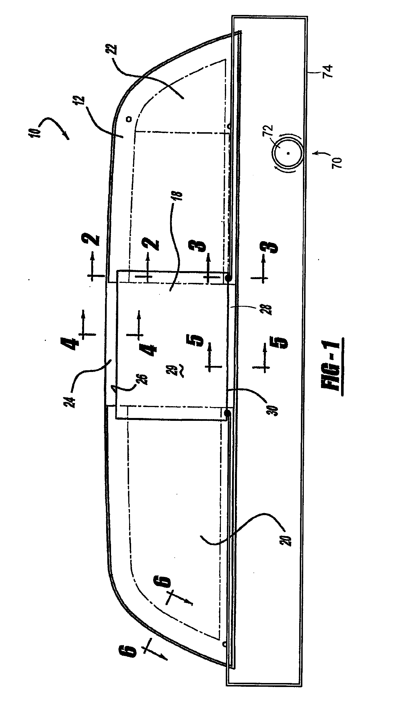
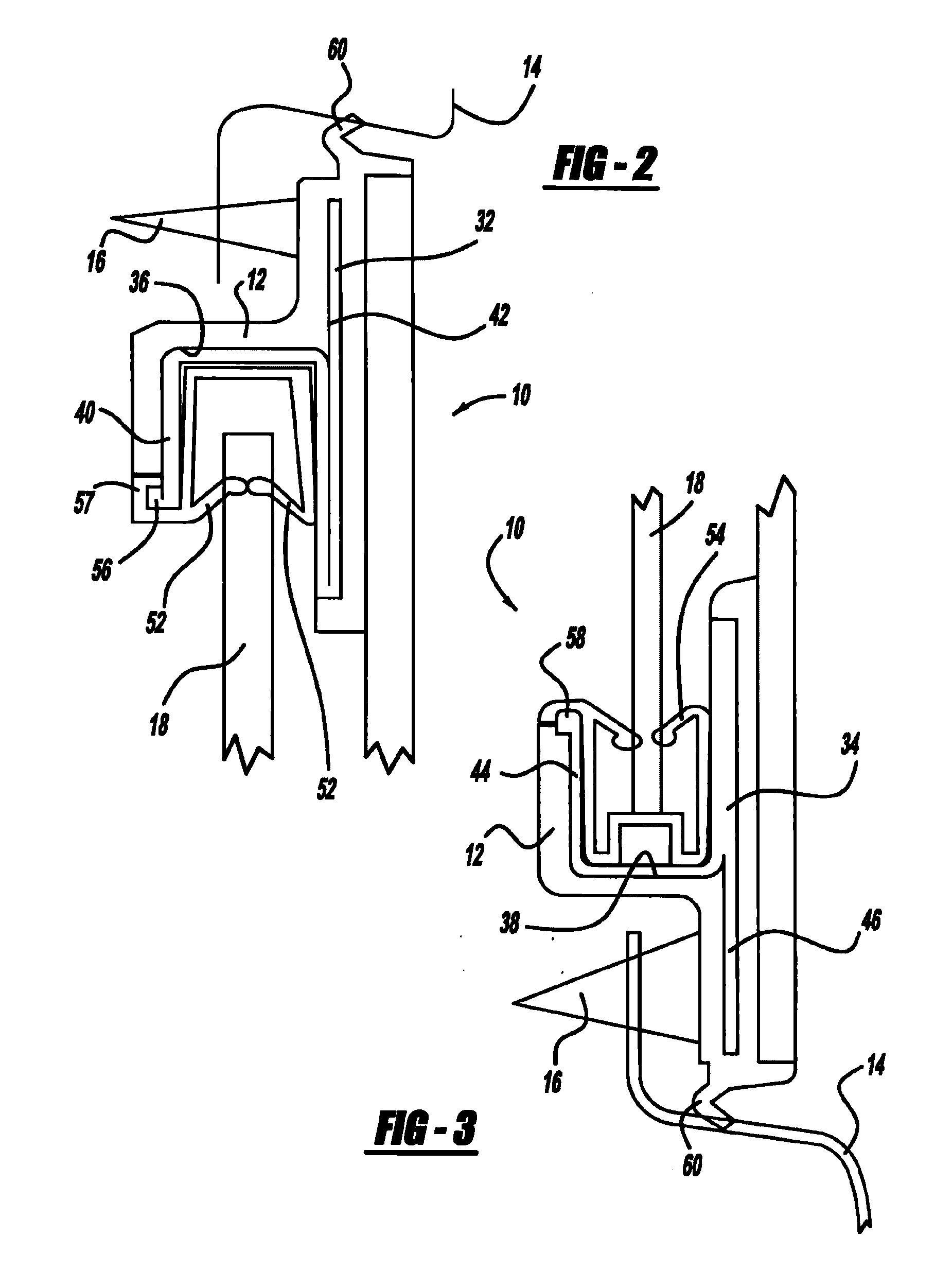
[0024]Window assemblies of the invention will have configurations and components determined, in part, by the intended application and use environment. References to direction and position, unless otherwise indicated, refer to the orientation of the window assembly in the drawing under discussion. In general, “exterior” refers to a direction or position outwardly of the space enclosed by the wall or structure in which the window is installed, e.g., outside the passenger compartment of a motor vehicle. Correspondingly, “inward” or “interior” refers to a direction in or into the passenger compartment or other such space. The term “inboard” is used here (i.e., in this description of the disclosed window assemblies and in the appended claims) to describe a lateral position or location, e.g., the location of the vertical edge of a fixed or stationary pane which is proximate to the slider pane. As viewed in FIG. 1, for example, inboard refers to the lateral position of a feature, i.e., the...


PUM


Abstract

A window assembly includes fixed panes, a sliding pane, and a vehicle mounting frame. The mounting frame includes a single, unitary, substantially full-circumference frame member and reinforcement at least partly embedded in the frame member. Interior surfaces of the fixed panes are bonded to the frame member, and the exterior surface of the fixed panes are free of the frame. At least a laterally outboard portion of the peripheral edge of each fixed pane is covered by the frame member. A surface of the window assembly for at least a laterally extending portion of the window assembly above or below the window opening.

Description

CROSS-REFERENCE[0001]The present application is a continuation of U.S. application Ser. No. 11 / 555,808 filed on Nov. 2, 2006, which is a non-provisional application that claims priority benefit of U.S. Provisional Application No. 60 / 839,083, filed Aug. 21, 2006. The present application claims priority to and the benefit of all the above-identified applications, whose disclosures are hereby expressly incorporated herein.INTRODUCTION[0002]The present invention is directed to multi-pane window assemblies suitable for use, for example, in motor vehicle bodies, and to the manufacture of such window assemblies. In particular, the invention is directed to multi-pane window assemblies presenting a substantially flush appearance in a window opening, supporting both fixed and sliding panes.BACKGROUND[0003]Window assemblies which are pre-assembled prior to installation are widely used in motor vehicle manufacture and other applications. Pre-assembly of the glazing unit for simple insertion int...

Claims


Application Information

Patent Timeline
Patent Type & Authority Applications(United States)
IPC IPC(8): B60J1/18B60J10/04
CPCB60J1/1853B60J10/0011E05Y2900/55E05D15/0652B60J10/04B60J10/18B60J10/74
Inventor CICALA, ROBERT JOHN
Owner PLASMAN US HOLDCO LLC
Why Eureka
Try Eureka