Electric parking brake device

a technology of parking brake and electric motor, which is applied in the direction of braking system, mechanical equipment, transportation and packaging, etc., can solve the problems of certain limit on downsizing devices, and achieve the effect of enhancing responsiveness

Inactive Publication Date: 2007-11-29
SAKAI TOMOYASU
View PDF7 Cites 6 Cited by
  • Summary
  • Abstract
  • Description
  • Claims
  • Application Information

AI Technical Summary

Benefits of technology

[0008]Accordingly, it is a primary object of the present invention to provide an improved electric parking brake device capable of being downsized as well as of enhancing the responsiveness at the time of the braking operation of a parking brake.
[0010]With this configuration, because the auxiliary force applying means is provided for conserving energy in the return direction of the at least one cable and for applying an auxiliary force, depending on the conserved energy, in the drawing direction of the at least one cable, the energy is conserved in the auxiliary force applying means at the time of the release operation (at the time of cable return) in which any substantial load is not imposed on the electric motor and the like, and the conserved energy can be utilized at the time of the braking operation of the at least one parking brake (at the time of cable drawing) in which a substantial load is imposed on the electric motor and the like. Thus, it becomes possible to make small the load imposed on the electric motor and the like. Further, because of the provision of the clutch mechanism which is capable of transmitting rotation in one direction only from the electric motor to the conversion mechanism, the braking state of the at least one parking brake can be held even when the application of electricity to the electric motor is discontinued, so that it becomes possible to make small the reduction ratio between the electric motor and the clutch mechanism. Further, it becomes possible to positively utilize the auxiliary force conserved in the auxiliary force applying means. Accordingly, it can be realized to downsize the parking brake device and to enhance the responsiveness at the time of the braking operation of the at least one parking brake.

Problems solved by technology

However, in the aforementioned prior art parking brake device, when the parking brakes are brought into the braking state, the cables have to be tensioned against their tensions, and this applies a substantial load to the electric motor and the reduction mechanism, so that there has been a certain degree of limitation on downsizing the device.

Method used


Image

  • Electric parking brake device
  • Electric parking brake device
  • Electric parking brake device

Examples


first embodiment

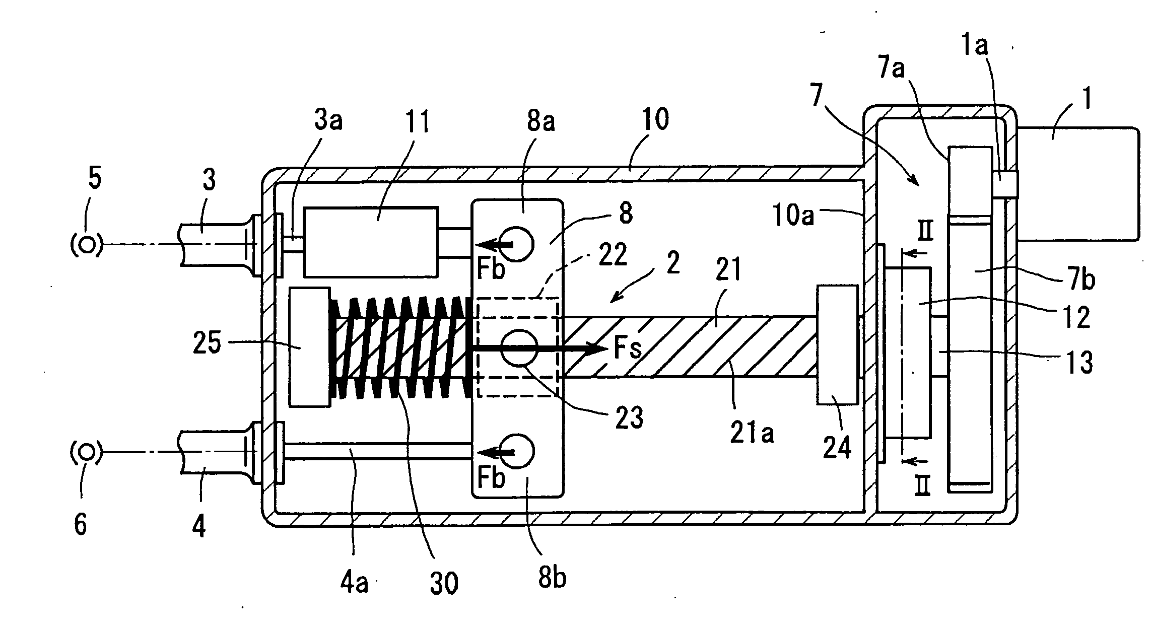
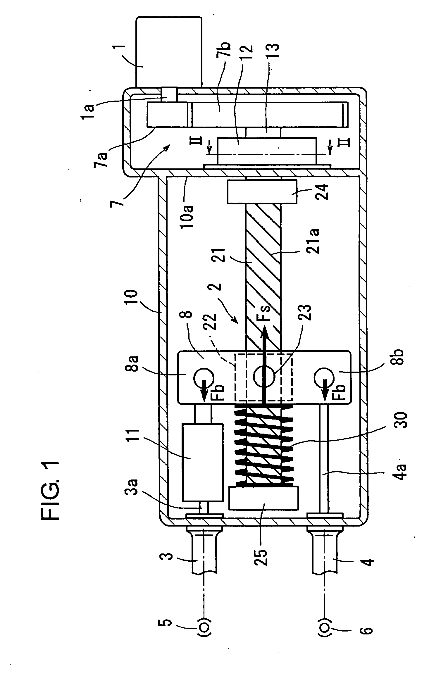
[0019]Hereafter, an electric parking device in a first embodiment according to the present invention will be described with reference to FIGS. 1 to 5. The electric parking brake device in the present embodiment comprises a housing 10, an electric motor 1 mounted on the housing 10, a conversion mechanism 2 for converting the rotational drive force of the electric motor 1 into a linear drive force, and a pair of cables, each composed of outer and inner cables 3, 3a or 4, 4a, for transmitting the linear drive motion from the conversion mechanism 2 to a pair of parking brakes 5, 6 schematically illustrated herein. One-way clutch 12 as a clutch mechanism is provided between the electric motor 1 and the conversion mechanism 2, and an equalizer 8 as a movable member and a compression spring 30 made of an elastic member as auxiliary force applying means are provided between the conversion mechanism 2 and the cables. Further, a tension sensor 11 is provided between the equalizer 8 and one of...

second embodiment

[0041]The principal mechanical components of an automotive electric parking brake device in a second embodiment are the same as those in FIG. 1, as shown in FIG. 6. The same components as those in the first embodiment shown in FIG. 1 are designated by the same reference numerals as used in FIG. 1, and description thereof will be omitted for the sake of brevity.

[0042]In the automotive electric parking brake device in the second embodiment, a tension spring 31 is wound around the screw shaft 21 between the equalizer 8 and the bearing 24, and the tension spring 31 is secured to the bearing 24 at its one end and is hooked on the pivot pin 23. Thus, the equalizer 8 is urged by the auxiliary force Fs of the tension spring 31 in the drawing direction of the inner cables 3a, 4a (i.e., in the rightward direction as viewed in FIG. 6). In this parking brake device, the tension spring 31 is employed, so that the elastic force of the tension spring 31 can be used as the auxiliary force Fs. That ...

third embodiment

[0044]The principal mechanical components of an automotive electric parking brake device in a third embodiment are the same as those in FIG. 1, as shown in FIG. 7. The same components as those in the first embodiment shown in FIG. 1 are designated by the same reference numerals as used in FIG. 1, and description thereof will be omitted for the sake of brevity.

[0045]In the automotive electric parking brake device in the third embodiment, a torque spring 32 is interposed between an extreme end of the screw shaft 21 and the housing 10, wherein one end of the torque spring 32 is hooked on the extreme end of the screw shaft 21, while the other end of the torque spring 32 is fixed on the housing 10. The auxiliary force Fs of the torsion spring 32 applies a force to the screw shaft 12 in such a direction as to rotate the screw shaft 12 in the positive-going direction. This force is transmitted through the screw 21a and the nut 22, whereby the equalizer 8 is urged in the drawing direction o...


PUM


Abstract

An electric parking brake device comprises an electric motor, a conversion mechanism for converting a rotational drive force given by the electric motor into a linear drive force and a pair of cables (i.e., inner cables) connected to a pair of parking brakes, wherein the parking brakes are brought into a braking state when the cables are drawn in a drawing direction by the operation of the electric motor in a positive-going direction, but are brought into a release state when the cables are returned in a return direction by the operation of the electric motor in a reverse direction. Between the electric motor and the conversion mechanism, a clutch mechanism is provided for transmitting the rotation of the electric motor to the conversion mechanism, but for blocking the rotation transmission from the conversion mechanism toward the electric motor. An auxiliary force applying member comprising any one of a compression spring, a tension spring and a torsion spring is provided for applying an auxiliary force to the conversion mechanism when the same is operated to draw the cables in the braking operation of the cables.

Description

INCORPORATION BY REFERENCE[0001]This application is based on and claims priority under 35 U.S.C. 119 with respect to Japanese Application No. 2006-145320 filed on May 25, 2006, the entire content of which is incorporated herein by reference.BACKGROUND OF THE INVENTION[0002]1. Field of the Invention[0003]The present invention relates to an electric parking brake device which converts a rotational drive force of an electric motor to a linear drive force for transmitting the same to one or more parking brakes.[0004]2. Discussion of the Related Art[0005]Heretofore, there has been known an electric parking brake device described in Japanese unexamined, published patent application No. 2005-16600. The device is provided with an electric motor, a reduction mechanism for transmitting the rotational drive force of the electric motor at a reduced speed, a conversion mechanism for converting the rotational drive force from the reduction mechanism into a linear drive force, and cables for trans...

Claims


Application Information

Patent Timeline
Patent Type & Authority Applications(United States)
IPC IPC(8): F16D65/14F16D65/28
CPCB60T11/046B60T13/746F16D2125/60F16D2121/14F16D2121/24F16D65/28
Inventor SAKAI, TOMOYASU
Owner SAKAI TOMOYASU
Why Eureka
Try Eureka