Ion Mobility Separation Devices

a technology of mobility separation and separation device, which is applied in the direction of separation process, particle separator tube details, instruments, etc., can solve the problems of complicated aerodynamic flow, limited maximum sheath gas flow rate, and working device based on loscertales principles,

Active Publication Date: 2007-11-29
LABOWSKY MICHAEL J +1
View PDF7 Cites 15 Cited by
  • Summary
  • Abstract
  • Description
  • Claims
  • Application Information

AI Technical Summary

Benefits of technology

The technical effect of this patent is that it describes how to keep the airflow smooth when measuring gases in an analytical device. This helps ensure accurate results from the measurements.

Problems solved by technology

The technical problem addressed in this patent text relates to improving the performance of mass analysis devices used for detecting aerosol samples. These devices require high accuracy in measuring the concentration of ions and molecules in the air. However, there are limits to achievable resolution due to various factors like the width of the channels and the speed of the sheath gas flow. The solution proposed involves optimizing the resistivity ratiosyn and shelf-channel pressure drop rates to reduce loss of sensitivity and improve the detection of aerosol particles.

Method used


Image

  • Ion Mobility Separation Devices
  • Ion Mobility Separation Devices
  • Ion Mobility Separation Devices

Examples


Embodiment Construction

Three Element Devices

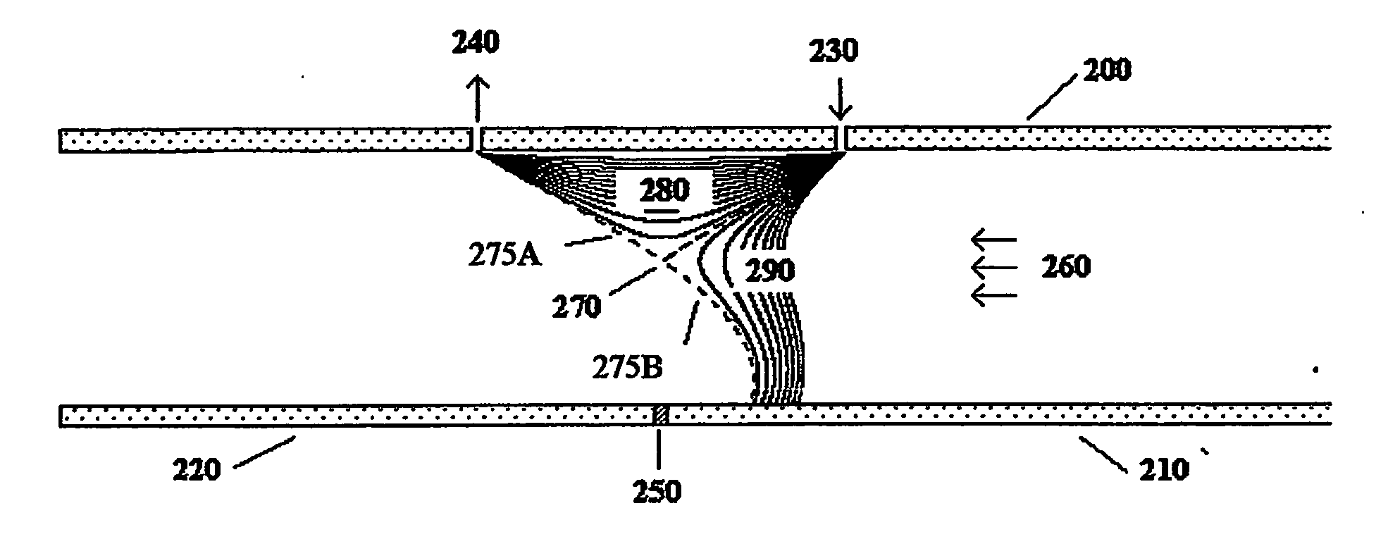
[0042] The present invention has many possible embodiments. The purpose of the following sections is to show a few of these embodiments which demonstrate how specially configured elements can be used to obtained the desired characteristics. Others embodiments should be obvious to those skilled in the art. FIG. 2 shows one embodiment of the current invention. The device shown is similar to the one shown in FIG. 1. It has a top plate (200) and a parallel bottom plate. In contrast to FIG. 1, the bottom “plate” has two elements (210,220). There is a voltage difference between the bottom left (220) and bottom right elements (210). A “junction” (250) separates the bottom left (220) and bottom right (210) elements and enables these elements to be at different voltages. To be considered a junction, the junction must be sufficiently near the analyzing region so the strong electrical fields near the junction affect the trajectories of the ions in the analyzing region. P...


PUM


Abstract

The invention describes a system and method to separate ions (and charged particles) suspended in gas based on their ion electrical mobility. Most common ion mobility analyzers involve two parallel plate (or concentric cylinder) elements (electrodes) between which is imposed an electrical field perpendicular to a sheath gas flow field between the cylinders. Separation occurs because high mobility ions tend to follow the electrical field while low mobility ions tend to follow the flow field. This invention describes various configurations of electrical elements and sheath gas flow fields for ion mobility separation devices with unique performance characteristics. These characteristics include devices in which: the ion inlet and outlet are on the same element; the inlet and outlet are at the same voltage; the outlet is upstream from the inlet; the outlet is on the axis; the inlet is on the axis; and the ions are focused on the outlet.

Description


Claims


Application Information

Patent Timeline
Owner LABOWSKY MICHAEL J
Why Eureka
Try Eureka