Endoscope image pickup optical system

an endoscope and optical system technology, applied in the field of endoscope image pickup optical system, can solve the problems of difficult diagnosis, difficult operation of optical system, and difficulty in determining the correct size of the endoscope, so as to reduce the outer diameter of the endoscope, increase the outer diameter, and increase the hardness of the knoop

Inactive Publication Date: 2005-06-14
OLYMPUS CORP
View PDF10 Cites 57 Cited by
  • Summary
  • Abstract
  • Description
  • Claims
  • Application Information

AI Technical Summary

Benefits of technology

[0048]Further, it is preferable in the present invention that the optical element closest to the object side in the image pickup optical system should be a negative lens having, in order from the object side, a plane surface and a concave surface directed toward the image side. In general, an endoscope comprises a wide-angle optical system providing a field angle of 100° or more. Therefore, if the optical element closest to the object side in the image pickup optical system is a plane-parallel plate, as shown in FIG. 11(b), the area 8 within the visual field defined on the viewing window by a bundle of rays incident on an effective image pickup area 10 (i.e. effective image area) of a solid-state image pickup device 9 becomes large. Consequently,

Problems solved by technology

On the other hand, diagnosis may be hindered by a scratch or chip on an image pickup optical element or foreign matter attached thereto that are so small as not to interfere with diagnosis in the past because of the high-resolution image quality.
Consequently, diagnosis may be hindered by a scratch or chip or foreign matter on an objective optical element that have heretofore presented no problem.
Among the causes of disturbing image quality arising from the presence of the above-described scratch or chip or foreign matter on the image pickup optical element, three causes due to the optical element closest to the object side in the image pickup optical system are frequently regarded as problematic.
However, because the washing water is lower in temperature than the viewing window, which has been heated by the body temperature, condensation occurs on the image-side surface of the optical element closest to the object side in the image pickup optical system.
Fogging of the optical element makes it impossible to obtain a favorable image.
However, if the front and second optical elements are cemented together to attain an airtight seal, the adhesive may enter the inside of a bundle of rays (hereinafter referred to as “within the visual field”) incident on the CCD by capillary action, causing flare, which gives rise to a problem.
Therefore, it costs a great deal to make repairs.
However, the adhesive applied to the periphery of the optical element closest to th

Method used


Image

  • Endoscope image pickup optical system
  • Endoscope image pickup optical system
  • Endoscope image pickup optical system

Examples


example 1

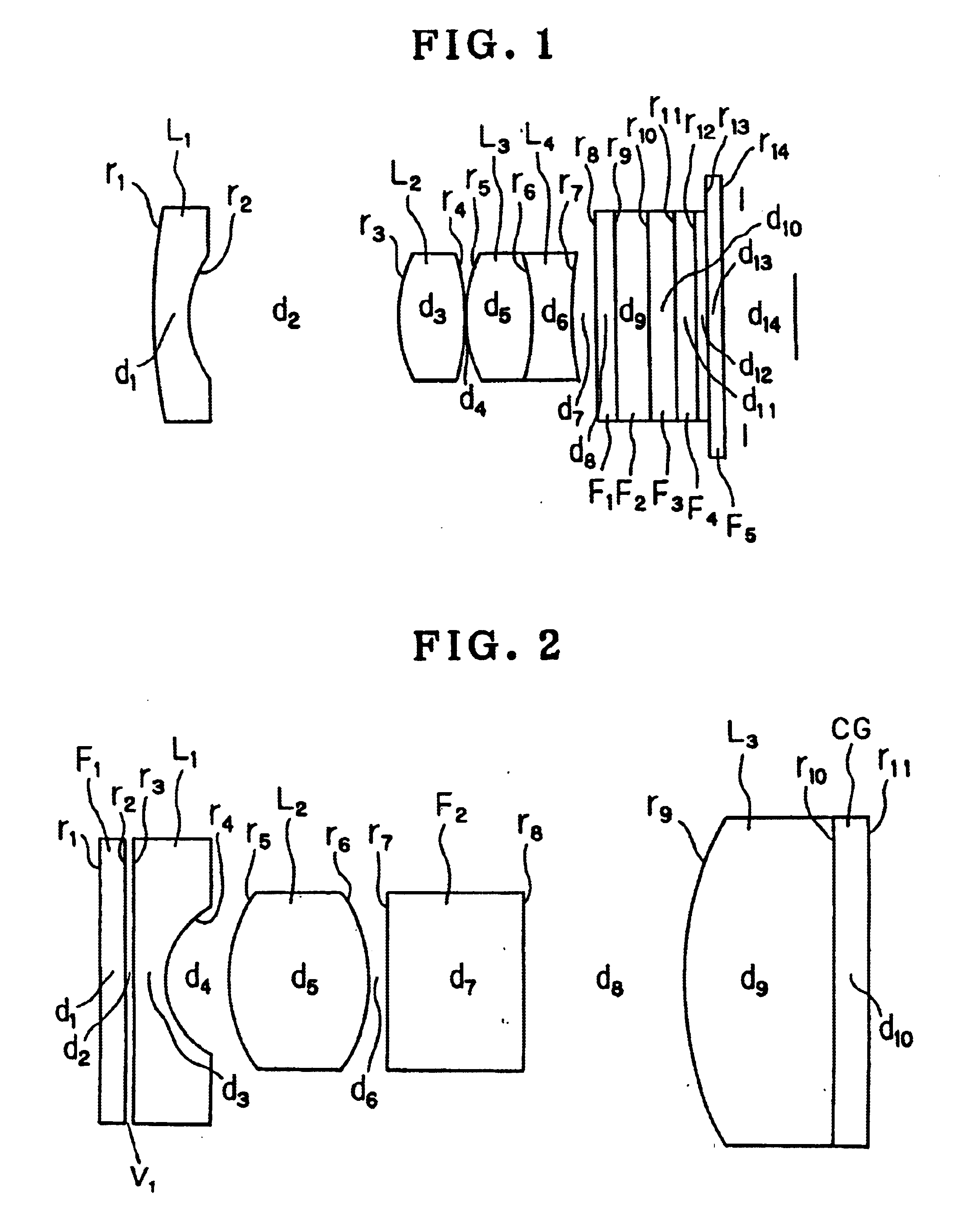
[0068]FIG. 1 shows a sectional view of a lens system constituting an optical system of an electronic camera according to Example 1. Example 1 has lens data as shown in Table 1, which will be shown later. In the table: f denotes the focal length of the entire system; 2ω denotes the field angle; FNo denotes the F-number; r1, r2 . . . denote the radii of curvature of lenses; d1, d2 . . . denote the spacings between lens surfaces and the lens spacings; nd1, nd2 . . . denote the refractive indices of the lenses for the d-line (587 nm); and νd1, νd2 . . . denote the Abbe's numbers of the lenses for the d-line (587 nm). The same shall apply hereinafter.

[0069]Example 1 comprises, in order from the object side, a negative meniscus lens L1 having a convex surface directed toward the object side, a double-convex positive lens L2, a cemented lens consisting of a double-convex positive lens L3 and a double-concave negative lens L4, plane-parallel plates F1 to F5, and a CCD. It should be noted th...

example 2

[0071]FIG. 1 shows a sectional view of a lens system constituting an endoscope optical system according to Example 2. Example 2 has lens data as shown in Table 2, which will be shown later.

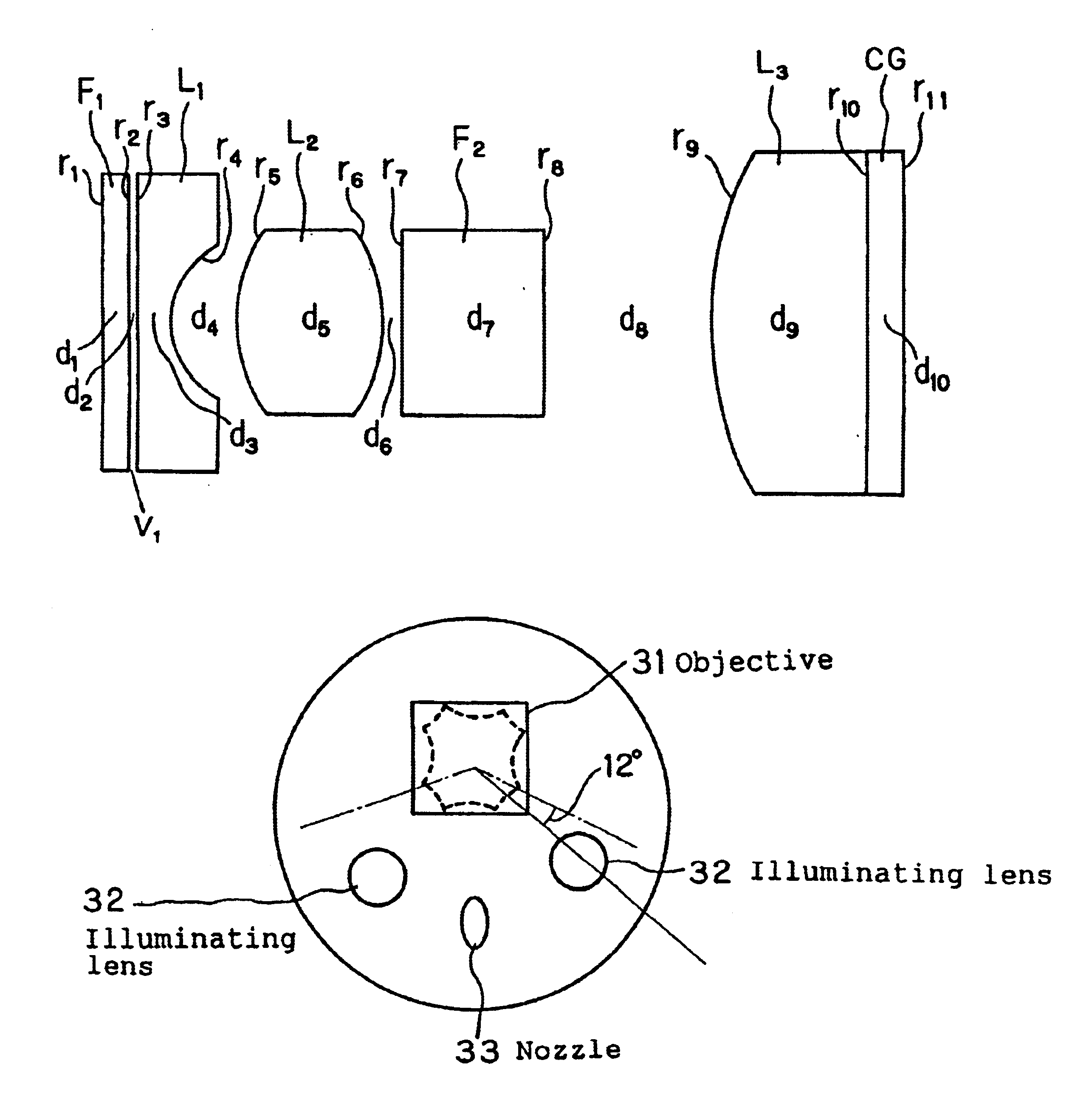
[0072]Example 2 comprises, in order from the object side, a plane-parallel plate glass or optical filter F1, a plano-concave negative lens L1, a double-convex positive lens L2, a filter F2 of plane-parallel plate for preventing infrared rays from entering the CCD, a convexo-plane positive lens L3, and a cover glass CG for the CCD. Among the optical elements, the optical filter F1 and the plano-concave negative lens L1 are quadrangular optical elements so as to be conformable to the shape of the effective image pickup-area of the CCD and to minimize the size of the image pickup optical system. It should be noted that the image-side plane surface of the convexo-plane plane positive lens L3 and the CCD cover glass CG are cemented together with an optical cement.

[0073]The CCD used in this image pickup...

example 3

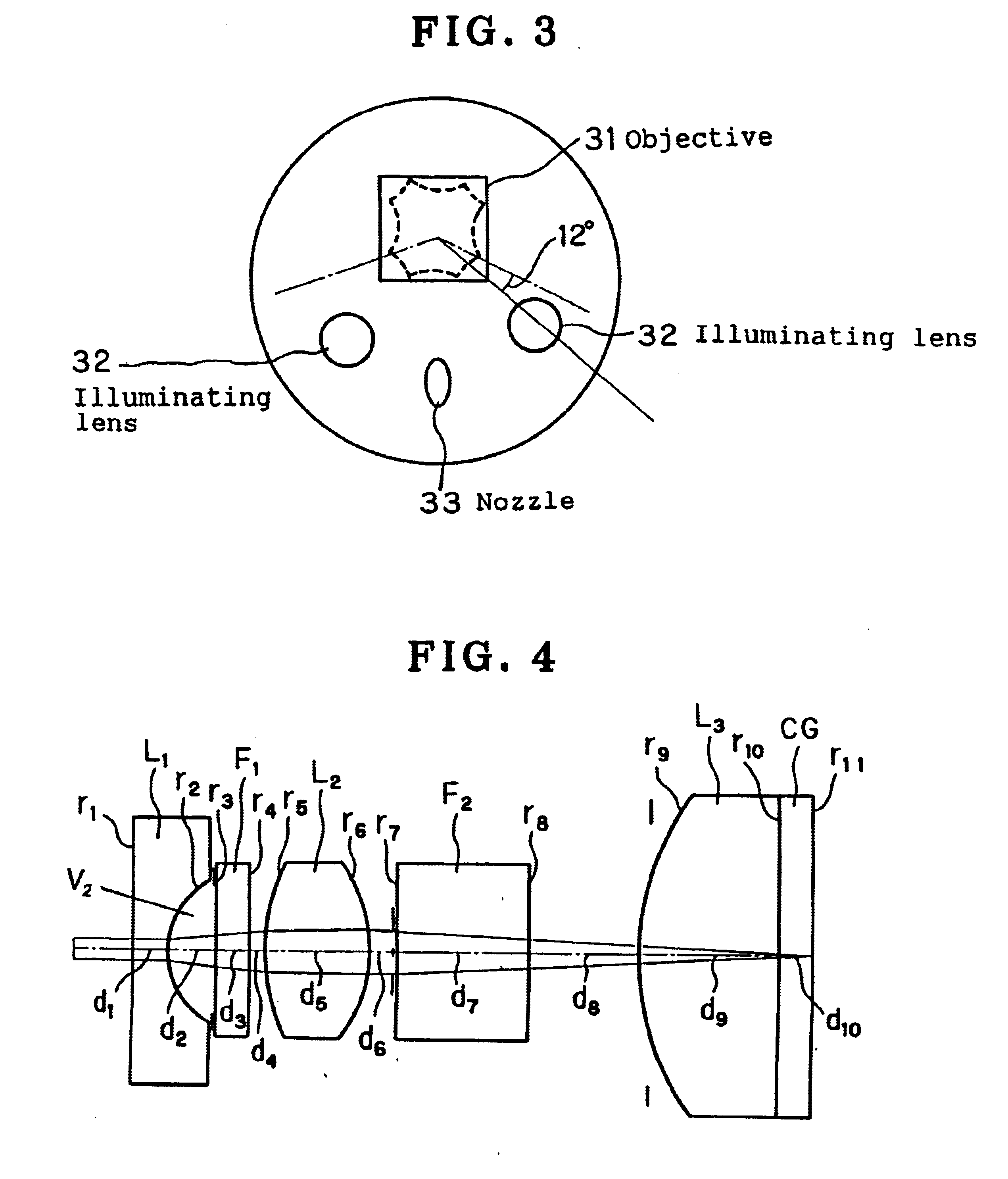
[0080]FIG. 4 shows a sectional view of a lens system constituting an endoscope optical system according to Example 3. Example 3 has lens data as shown in Table 3, which will be shown later.

[0081]Example 3 comprises, in order from the object side, a plano-concave negative lens L1, a plane-parallel plate F1, a double-concave positive lens L2, a filter F2 of plane-parallel plate for preventing infrared rays from entering the CCD, a convexo-plane positive lens L3, and a cover glass CG for the CCD. It should be noted that the image-side plane surface of the convexo-plane positive lens L3 and the CCD cover glass CG are cemented together with an optical cement.

[0082]The CCD in this image pickup optical system is a color CCD employing an interline type complementary color filter, which is a high-density CCD with an average pixel pitch of 2.8 μm.

[0083]The focal length of this image pickup optical system is 1.539 mm, and the F-number thereof is 5.6. The area of a light beam forming an image a...


PUM


Abstract

An endoscope optical system is capable of obtaining favorable endoscopic images at all times by overcoming the conventional disadvantages that diagnosis is hindered by image quality disturbance due to the increase in pixel density resulting from the reduction in pixel pitch of solid-state image pickup devices and also due to the conventional arrangement of an objective front optical element in an optical system having a short focal length or in an optical system having a large F-number. In an image pickup apparatus using a monochromatic high-density solid-state image pickup device in which the average pixel pitch (H+V)/2 of the pixel pitch H in the horizontal direction and the pixel pitch V in the vertical direction with respect to the monitor scanning line is not more than 4.65 μm, or using an interline type color high-density solid-state image pickup device in which the average pixel pitch (H+V)/2 is not more than 3.1 μm, the volume V1 of an air layer between a plane-parallel plate (F1) closest to the object side in the image pickup optical system and a piano-concave negative lens (L1) satisfies the following condition:
V1<4 mm3  (1)

Description

TECHNICAL FIELD[0001]The present invention relates to an endoscope image pickup optical system for forming an image on an electronic image pickup device. More particularly, the present invention relates to an electronic image pickup optical system providing a favorable image free from image quality disturbance in electronic cameras and endoscopes using a high-density solid-state image pickup device.BACKGROUND ART[0002]As a means for examining and treating the inside of a body cavity or the like by inserting an insert part into the body cavity or the like, a video endoscope is widely used, which has a solid-state image pickup device (hereinafter referred to as “CCD”) incorporated in a distal end portion thereof.[0003]There are two image pickup systems available to video endoscopes using a single CCD.[0004]One of them is a field sequential image pickup system in which R, G and B light are sequentially applied to a subject, and reflected light from the subject is imaged by using a mono...

Claims


Application Information

Patent Timeline
IPC IPC(8): G02B23/24G02B17/08H04N5/225
CPCG02B9/12G02B23/2484G02B23/243H04N2005/2255H04N23/555G02B27/00
Inventor HOMMA, HIROYUKIKONNO, SAYAKA
Owner OLYMPUS CORP
Why Eureka
Try Eureka