
Electric percussion instruments

a technology of electric percussion and percussion drums, applied in the field of musical instruments, can solve the problems of loss of fidelity on toms and bass drums, more complicated, and high cost of close micing

Inactive Publication Date: 2006-02-02
FREITAS PAUL JOHN
View PDF25 Cites 59 Cited by
  • Summary
  • Abstract
  • Description
  • Claims
  • Application Information

AI Technical Summary

Benefits of technology

[0016] It is an object of the invention to provide electric percussion instruments that use vibrating surfaces to generate sound directly as well as electrical waveforms for recording or amplification purposes, thus combining the advantages of acoustic and electronic percussion instruments. This waveform is to be generated by creating a voltage difference between a layer of the vibrating surface portion and a sensor portion placed in close proximity. This sensor is connected to a voltage source through a source of electrical impedance (such as a resistor). When the electric percussion instrument receives an activating action from a performer, such as a stick strike, the voltage difference between vibrating surface and sensor will oscillate in response, and that voltage oscillation can be sent through an electronic circuit to external recording or amplification equipment.
[0017] It is a further object of the invention to allow for the use of any number of vibrating surfaces, to provide better acoustic range and better emulate acoustic percussion instruments.
[0018] It is another object of the invention to provide a system that can act as an electrical transducer, producing an electrical waveform as an output, an acoustic transducer, producing sound directly, or any combination of the two. For example, by choosing more solid vibrating surface materials, the invention may produce a large amount of direct sound output, as an acoustic percussion instrument would do. The percussionist may thus monitor the waveforms produced by the instruments by listening to them directly, as he / she would do for acoustic instruments, as well as through speakers or headphones, as he / she would do for electronic instruments. If the vibrating surface is made instead of materials with a large number of holes, such as a meshlike material with wide spacings in the weave, the invention will produce much less direct sound, but will still produce electrical signals that can produce audio waveforms in recording or amplification equipment. A percussionist can monitor his / her performance through loudspeakers or headphones.
[0019] Yet another object of the invention is to provide electric percussion instruments that can be produced and sold at a cost lower than that of traditional acoustic instruments plus the high quality microphones needed to record or amplify their sound.

Problems solved by technology

It is also more complicated, due to the number of microphones needed.
Close micing can be very costly, especially if high quality microphones are required (as is often the case for cymbals).
Some loss of fidelity is experienced on toms and bass drums because the microphone only captures the sound from the head being struck.
For greatest fidelity in an amplified performance or recording session, they require a large number of microphones, which can be quite expensive.
Arranging these microphones requires great expertise, and can be quite time consuming.
The fact that microphones can pick up any and all sounds present, not just the percussion instrument sounds, can cause significant problems for sound engineers.
Another problem with acoustic instruments is that they can be very loud, often too loud for other musicians performing with a percussionist, or for neighbors of a percussionist practicing at home.
Elaborate muting systems have been devised, such as plexiglass shields and drumhead muffling devices, but these often change the sound of the instruments to an unacceptable degree.
Using less force to play the instrument changes the playability of the instruments as well as their acoustic output, and is generally not a viable solution for volume problems.
Electronic percussion instruments have a number of drawbacks that make them unacceptable to large numbers of musicians.
First and foremost, they lack the range and depth of acoustic instruments.
This repetetiveness can be unpleasant to many listeners.
Adding extra triggers to pads, or making them pressure sensitive, does little to alleviate this problem.
Electronic percussion instruments also often lack the physical response characteristics (or “feel”) of their acoustic counterparts, which can limit their playability.
These systems do not have the dynamic range of an ordinary microphone.
Furthermore, the speaker cones tend to be so large that they cannot be used in double-headed drums, because they disrupt the sound waves inside drums to an unacceptable degree.
Pickup-based systems are at a disadvantage because they require special drumheads or cymbals that do not well emulate traditional acoustic drumheads or cymbals.
Furthermore, the pickups tend to capture vibrations at a single point only, rather than sample the vibrational state of an entire cymbal or drumhead, as the sound from an acoustic instrument does.
Furthermore, a single pickup is often very dense compared to a drumhead or cymbal.
Placing a single pickup on a drumhead breaks the vibrational symmetry of the head, which tends to create a vibrational node (or dead spot) at that point.
The single pickup can thus destroy the vibrational fidelity of a drumhead.
The vibration of a whole drumhead or cymbal requires an impractical and costly number of pickups, as well as a complicated mixing aparatus.

Method used


Image

  • Electric percussion instruments
  • Electric percussion instruments
  • Electric percussion instruments

Examples


Embodiment Construction

Double-Headed Electric Drum

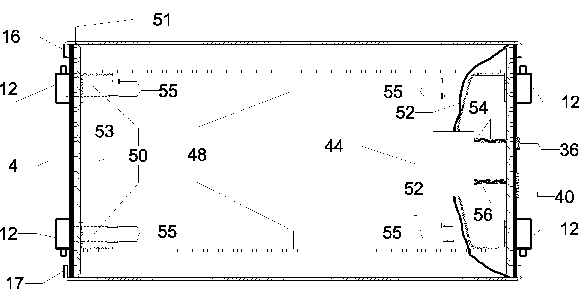
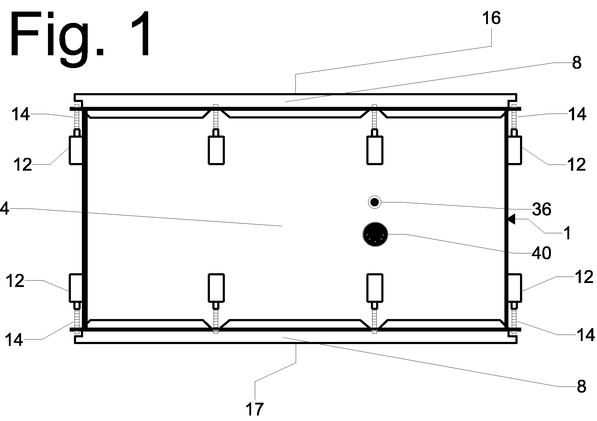
[0030] Referring now to the drawings, FIG. 1 depicts an embodiment of the invention, a double-headed electric drum 1. It consists of a cylindrical shell assembly 4 capped on top by a batter drumhead assembly 16, and on the bottom by a resonant drumhead assembly 17. The drumhead assemblies 16 and 17 are held taut on the drum by metal hoops 8, which are attached to the shell assembly by threaded tension rods 14 screwed into metal lugs 12. In this embodiment, there are six evenly-spaced lugs per shell end attached to the shell assembly. FIG. 1 also depicts an audio output jack 36, which is used to connect the drum to industry standard recording and amplification equipment. In this embodiment, the audio connection is through a standard ¼″ instrument cable (not shown). Power is supplied to the drum through the power input port 40, which connects to widely available grounded DC power supplies through a cable (not shown).

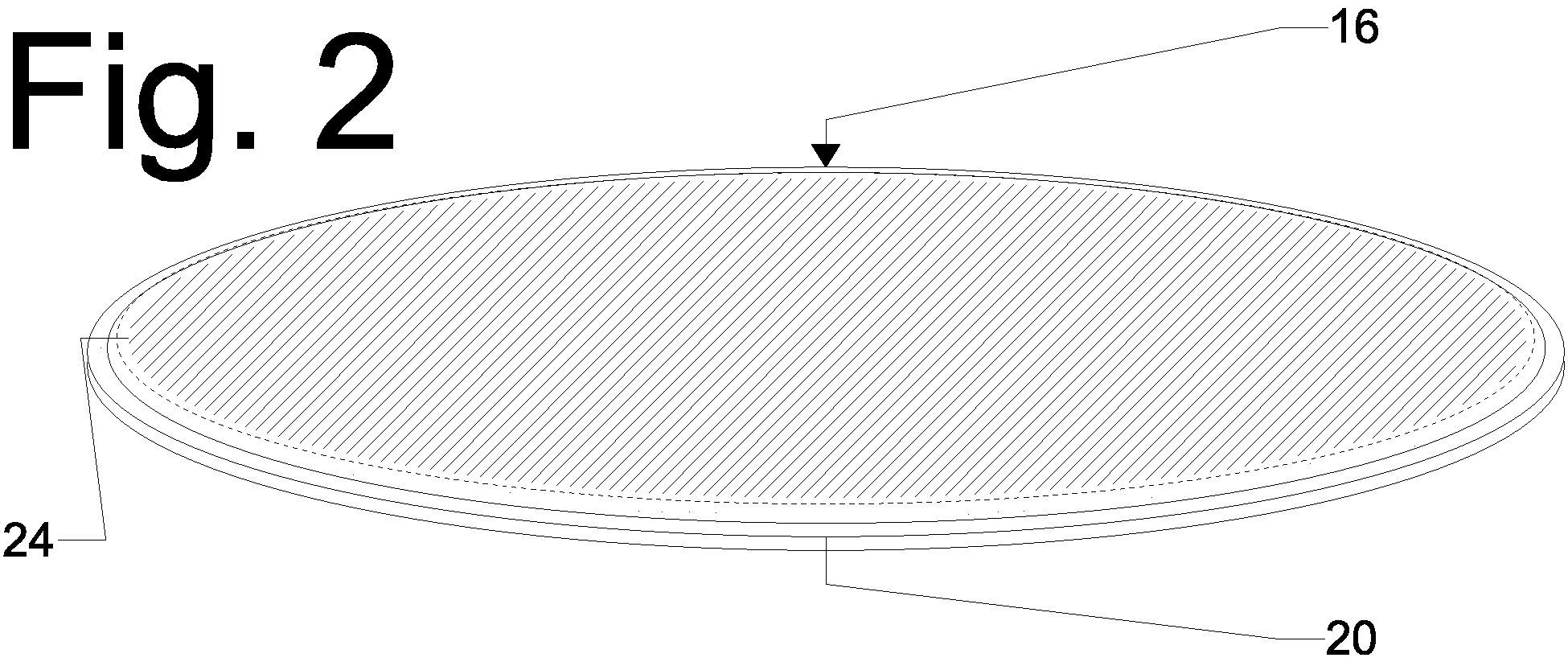
[0031]FIG. 2 depicts a perspective view...


PUM


Abstract

An electric musical instrument transducer contains one or more air gapped parallel plate variable capacitors. Each variable capacitor in the transducer has one plate that comprises, covers, or is embedded within an acoustically emitting vibrating surface on a musical instrument (such as a drumhead or soundboard) while the other plate is a rigid surface held a fixed distance away. When the instrument is played, the vibrating surface causes vibrations directly (without using airborne sound as an intermediary) in the non-fixed plates of the variable capacitors, thus causing time-varying voltage oscillations in the variable capacitors that directly reflect the vibrational state, and therefore the sound, of the instrument. These voltage oscillations are then converted to signals that can be used by audio recording and amplification equipment.

Description

BACKGROUND OF INVENTION [0001] This invention relates generally to the field of musical instruments, more particularly to an improved set of electric percussion instruments better adapted to interface with electronic recording and amplification equipment. There are two different models for percussion instruments in common usage at the time of this writing: acoustic and electronic. There is also a third model, electric percussion, which is less widely used. This invention relates to the third category. For completeness, all three categories will be discussed here. Acoustic Percussion Instruments [0002] Acoustic percussion instruments include a number of different types of drums (such as snare, tom, bass, conga, djembe, etc.) as well as cymbals (such as hi-hat, crash, ride, gong, etc). Acoustic percussion instruments can be widely varied, such as temple blocks and cowbells, but drums and cymbals are of particular interest to musicians. Usually a number of acoustic percussion instrume...

Claims


Application Information

Patent Timeline
Patent Type & Authority Applications(United States)
IPC IPC(8): G10H3/00
CPCG10H3/12G10H3/10
Inventor FREITAS, PAUL JOHN
Owner FREITAS PAUL JOHN
Learn More