
Stepping actuator and method of manufacture therefore

a technology of stepping actuators and actuators, which is applied in the direction of piezoelectric/electrostrictive device details, instruments, device details, etc., can solve the problems of complex geometries, complex operations required to create corrugation in flexible electrodes, and inability to construct devices in dimensions suitable for miniaturized integrated circuits, biomedical applications, or mems structures, etc., to achieve the effect of reducing air gaps, reducing pull-in voltage, and increasing actuating for

Inactive Publication Date: 2007-09-04
WAN CHANG FENG
View PDF43 Cites 60 Cited by
  • Summary
  • Abstract
  • Description
  • Claims
  • Application Information

AI Technical Summary

Benefits of technology

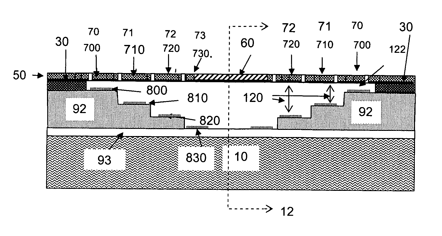
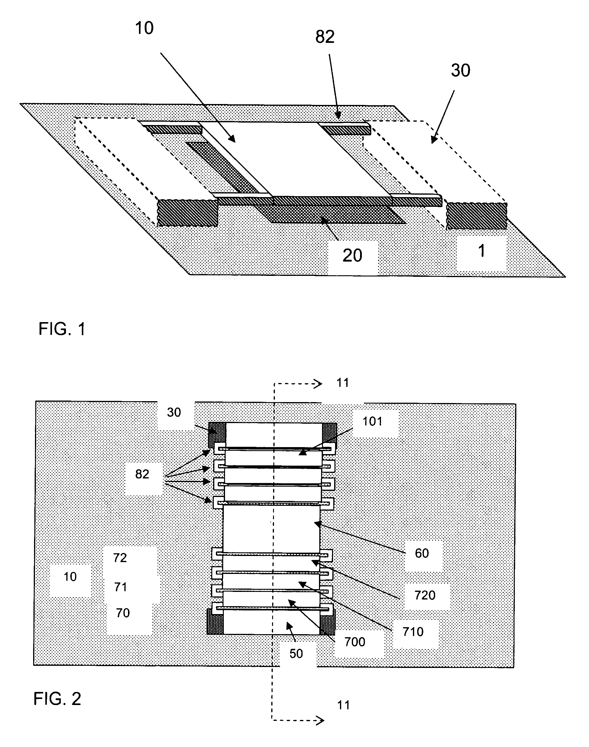
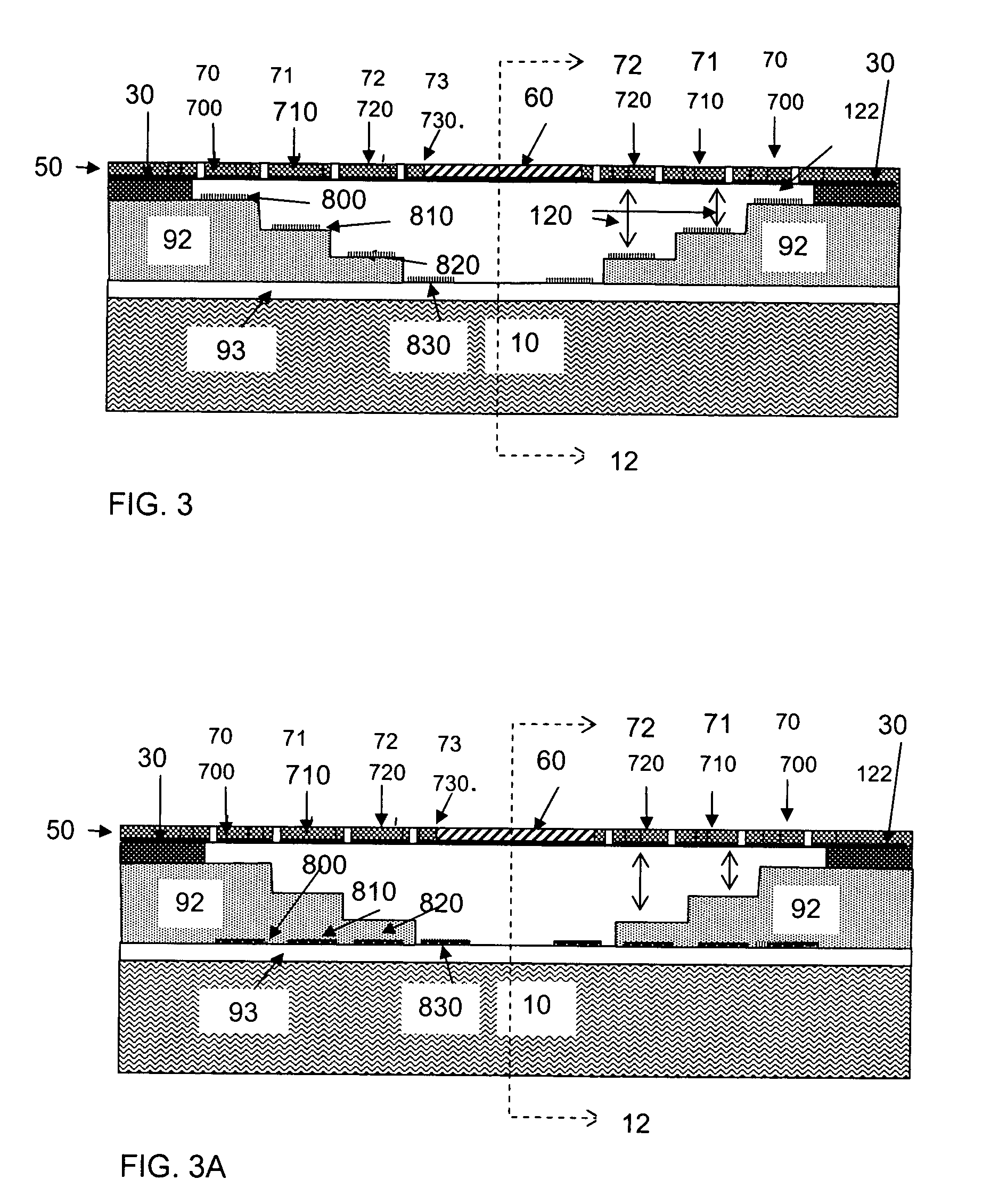
[0010]An embodiment of the present invention provides a stepping actuator that is capable of realizing vertical (to the surface of the substrate) displacements in precise, incremental steps. Each stepping motion is due to the pull-in of a pair of the many sub-actuators in the stepping actuator. The sub-actuators are parallel-plate electrostatic actuators, and they have graduated air gaps that subdivide the full displacement range of the stepping actuator. The actuation is by applying a voltage higher than the pull-in voltages so that their upper, movable electrodes come in contact with the fixed electrodes. This moves the rest of movable electrodes one incremental air gap, reduces the air gaps, lowers the pull-in voltage, and increases the actuating force in a fashion similar to the zipping actuators. More importantly, each step of actuation of the incremental displacement is dependent on incremental step height of the fixed electrodes only, not on the spring constants or mechanical properties of the material. This allows precision positioning that is independent of the exact mechanical properties of the material. This also allows both digital output and input.
[0011]A slew of innovative MEMS devices can be made by from utilizing or incorporating the stepping actuator. They are referred to as stepping actuator devices hereon. They can be operated in digital fashion, using a single voltage slightly higher than the pull-in voltage. Additionally, a method is also provided for fabricating and packaging the stepping actuator devices. It uses surface micromachining technique to fabricate and packaging the stepping actuator devices from single-crystal silicon, which is essential to high precision and stress-free microstructures.

Problems solved by technology

These devices work well for typical motive applications, but these devices cannot be constructed in dimensions suitable for miniaturized integrated circuits, biomedical applications, or MEMS structures.
However, some of these devices incorporate complex geometries using relatively difficult micro-fabrication techniques.
Complex operations are required to create corrugations in the flexible electrodes.
Further, due to manufacturing process and material variations, size and shape of the air gap can vary substantially from device to device, making operation erratic.
Thus there is positive feedback in this system, and at some critical voltage, the system goes unstable, and the air gap collapses to zero.
Such non-linear behaviors present a challenge to many MOEMS (Micro-Optical-Electro-Mechanical-System) applications requiring accurate positioning, including tunable Fabry-Perot filter and vertical cavity surface emitting laser (VCSEL), used for wavelength band selection in optical communications.
The accuracy requirement can only be met with closed-loop control schemes.
In addition, the tuning range of the displacement is limited to a few micrometers, which restricts MOEMS devices to the visible or near IR (Vis-NIR) applications.
The voltage is too high and needs to be decreased.

Method used


Image

  • Stepping actuator and method of manufacture therefore
  • Stepping actuator and method of manufacture therefore
  • Stepping actuator and method of manufacture therefore

Examples


Embodiment Construction

[0038]In the following detailed description, numerous specific details are set forth in order to provide a thorough understanding of the invention. However, it will be understood by those skilled in the art that the present invention may be practiced without these specific details. In other instances, well-known methods, procedures, components and circuits have not been described in detail so as not to obscure the present invention.

[0039]Some portions of the detailed description that follows are presented in terms of algorithms and symbolic representations of operations on data bits or binary digital signals within a computer memory. These algorithmic descriptions and representations may be the techniques used by those skilled in the data processing arts to convey the substance of their work to others skilled in the art.

[0040]An algorithm is here, and generally, considered to be a self-consistent sequence of acts or operations leading to a desired result. These include physical mani...


PUM


Abstract

An embodiment of the present invention provides a stepping actuator, comprising a suspended membrane comprising a plurality of movable electrodes connected by plurality of spring hinges to a payload platform; and anchors connecting said membrane to a substrate, said substrate comprising a plurality of fixed electrodes; wherein said movable electrodes of said suspended membrane and said fixed electrodes from said substrate form parallel-plate electrostatic sub-actuators.

Description

CROSS-REFERENCE TO RELATED APPLICATIONS[0001]This application claims the benefit of provisional patent application No. 60 / 534,302, filed Jan. 5, 2004 and provisional patent application No. 60 / 559,693 filed Apr. 2, 2004 and provisional patent application No. 60 / 566,901 filed Apr. 30, 2004 and provisional patent application No. 60 / 575,986 filed Jun. 1, 2004, and provisional patent application 60 / 607,723 filed Sep. 7, 2004.BACKGROUND[0002]Electrostatic forces have been used to move structures. Traditional electrostatic devices were constructed from laminated films cut from plastic or Mylar materials. A flexible electrode was attached to the film, and another electrode was affixed to a base structure. Electrically energizing the respective electrodes created an electrostatic force attracting the electrodes to each other or repelling them from each other. A representative example of these devices is found in U.S. Pat. No. 4,266,399. These devices work well for typical motive applications...

Claims


Application Information

Patent Timeline
Patent Type & Authority Patents(United States)
IPC IPC(8): H02N1/00G02B26/00H01H59/00
CPCH02N1/006H01G5/16H01G5/38
Inventor WAN, CHANG-FENG
Owner WAN CHANG FENG
Learn More