
Methods and Systems for Analyzing Samples Using Particle Irradition

Inactive Publication Date: 2007-11-29
BOARD OF RGT THE UNIV OF TEXAS SYST
View PDF9 Cites 3 Cited by
  • Summary
  • Abstract
  • Description
  • Claims
  • Application Information

AI Technical Summary

Benefits of technology

[0016] The terms “a” and “an” are defined as one or more unless this disclosure explicitly requires otherwise.
[0017] The term “substantially,”“about,” and its variations are defined as being largely but not necessarily wholly what is specified as

Problems solved by technology

While a conventional PIXE system can provide some analysis of samples, the current design has many limitations.
The most significant drawbacks include their size and the cost of the individual components.
These limitations have restricted the use of the PIXE system to private and research domains located in remote locations.
Therefore, samples are generally limited to frozen or dead samples.
The analysis of such samples does not take advantage of the occurrence of elemental redistribution commonly seen in live samples.
Additionally, real time information on the dynamics of metal distribution and accumulation found in live samples cannot be obtained.
Another restriction of the conventional PIXE system is that the system requires elaborate sample handling systems, such as a high vacuum for the sample chamber, and for biological samples, elaborate and expensive preparation.
The handling system may subject the sample to excessive forces, and may subsequently destroy the sample.
Similar to the forces applied by the handling system, the elaborate preparation of the samples may alter the sample, and thus, may cause an inaccurate or an incomplete analysis.
The referenced shortcomings are not intended to be exhaustive, but rather are among many that tend to impair the effectiveness of previously known techniques for analyzing samples using a PIXE system; however, those mentioned here are sufficient to demonstrate that the methodologies appearing in the art have not been altogether satisfactory and that a significant need exists for the techniques described and claimed in this disclosure.

Method used


Image

  • Methods and Systems for Analyzing Samples Using Particle Irradition
  • Methods and Systems for Analyzing Samples Using Particle Irradition
  • Methods and Systems for Analyzing Samples Using Particle Irradition

Examples


examples

[0054] The following examples are included to demonstrate specific embodiments of this disclosure. It should be appreciated by those of ordinary skill in the art that the techniques disclosed in the examples that follow represent techniques discovered by the inventors to function well in the practice of the invention, and thus can be considered to constitute specific modes for its practice. However, those of ordinary skill in the art should, in light of the present disclosure, appreciate that many changes can be made in the specific embodiments which are disclosed and still obtain a like or similar result without departing from the spirit and scope of the invention.

Alpha Emitting Isotopes

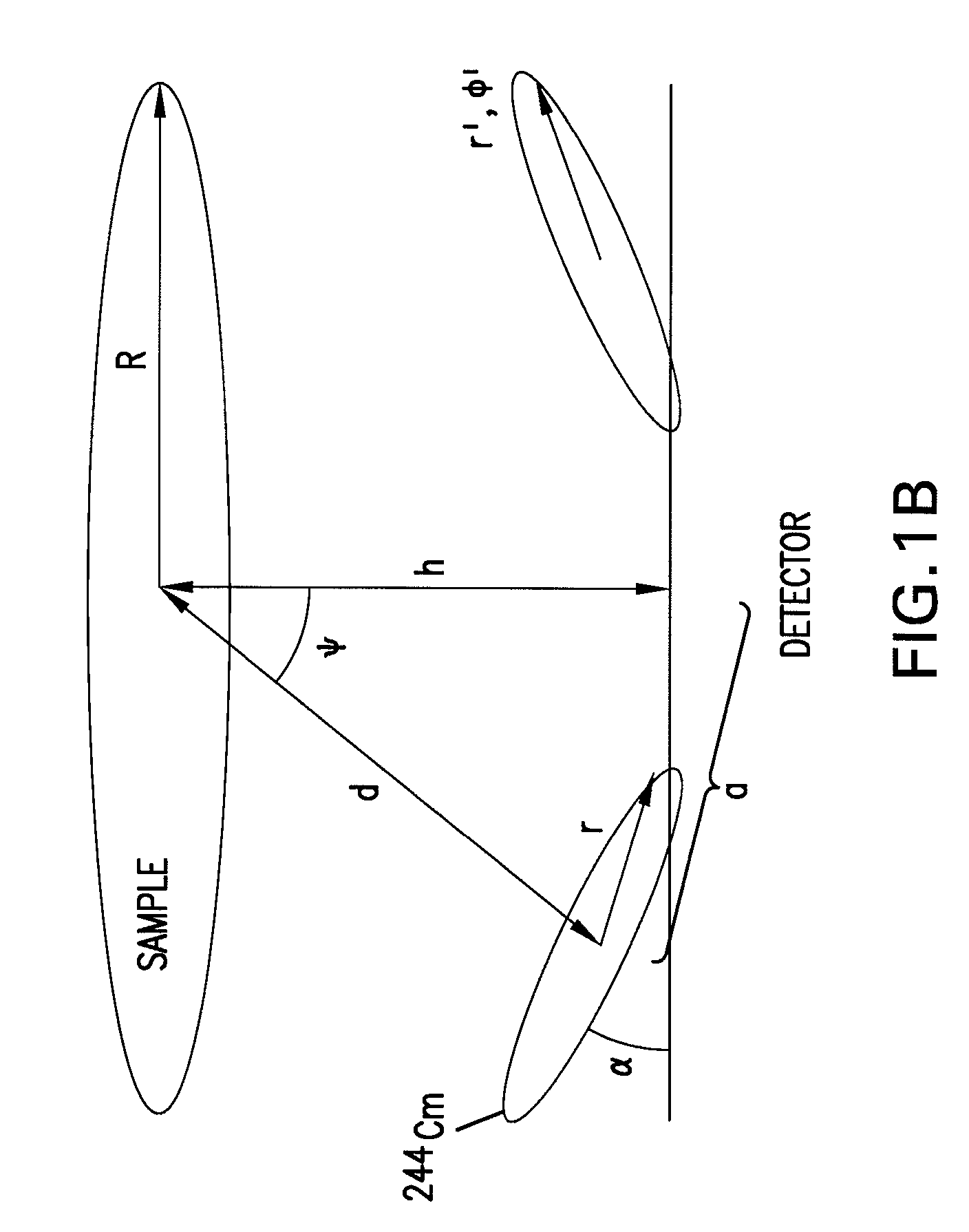
[0055] The use of a high-strength, alpha emitting isotope can provide a full analysis of a sample, without altering or destroying a sample in a cost-effective and efficient manner. In particular, alpha-emitting isotopes have a naturally larger beam spot size and with intensities that are orders o...


PUM


Abstract

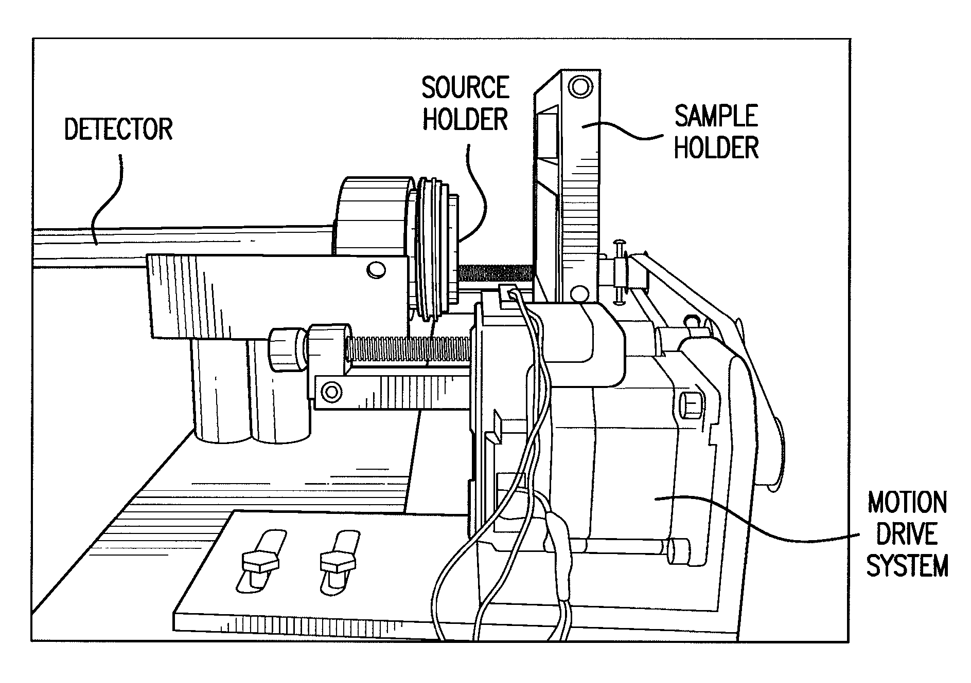
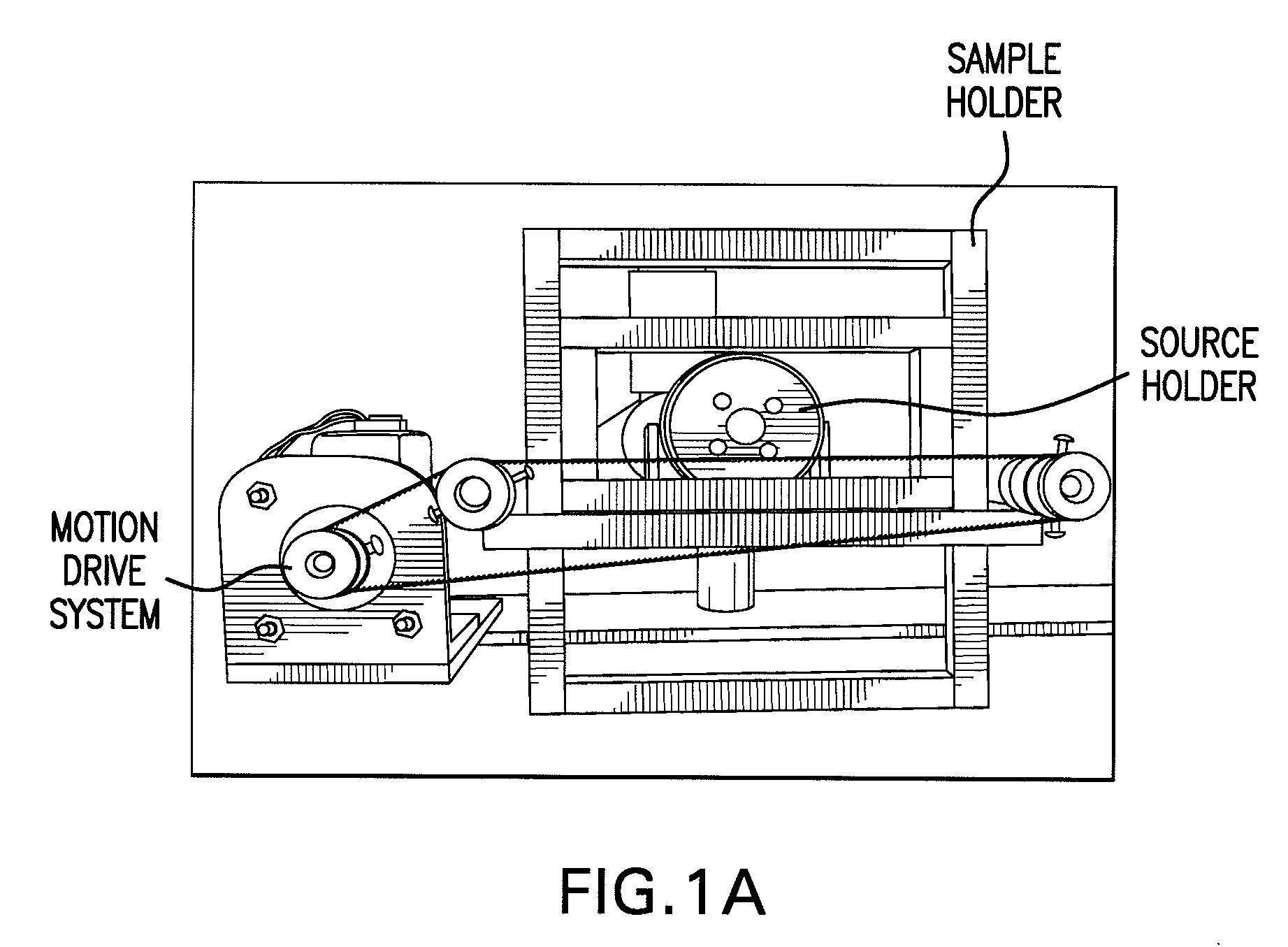
Systems and methods for an in situ, non destructive analysis of organic or inorganic material are disclosed. In one respect, a particle induced x-ray emission system, having a footprint of less than one square meter, includes a sample holder supporting a sample, a source holder supporting one or more radioactive source and a detector. A radioactive transmission from the one or more radioactive source to the sample results in a fluorescent emission of the sample and collected by the detector. In one respect, fluorescent emission may be used to determine elements found in the sample. Additionally, the amounts of each of the determined elements found in the sample may also be determined.

Description

[0001] This application claims priority to provisional patent application Ser. No. 60 / 778,865 filed Mar. 3, 2006, entitled, “Methods and Systems for Analyzing Samples Using Particle Irradiation” by Tarawneh et al. The entire text of the above-referenced disclosure, including figures, is specifically incorporated by reference herein without disclaimer.STATEMENT AS TO RIGHTS TO INVENTIONS MADE UNDER FEDERALLY-SPONSORED RESEARCH AND DEVELOPMENT [0002] Aspects of this invention were made with government support of the National Science Foundation, grant number DBI-0330815. Accordingly, the government may have certain rights in this invention.BACKGROUND OF THE INVENTION [0003] 1. Field of the Invention [0004] The present invention relates generally to sample analysis. More particularly, the present disclosure relates to methods and systems for in situ, non-destructive analysis of organic or inorganic samples. [0005] 2. Description of Related Art [0006] Particle induced x-ray emission (PIX...

Claims


Application Information

Patent Timeline
IPC IPC(8): H05G2/00
CPCG01N23/2257
Inventor TARAWNEH, CONSTANTINEDASGUPTA-SCHUBERT, NABANITAPERSANS, MICHAEL
Owner BOARD OF RGT THE UNIV OF TEXAS SYST
Learn More