Method and apparatus for trimming the edges of a float glass ribbon

a technology of float glass ribbon and trimming method, which is applied in the direction of control devices of furnaces, lighting and heating apparatus, furnace components, etc., can solve the problems of preheating and the method according to u.s. pat. no. 5 not being suitable for trimming float glass,

Inactive Publication Date: 2007-11-29
JENOPTIK AUTOMATISIERUNGSTECHN
View PDF11 Cites 30 Cited by
  • Summary
  • Abstract
  • Description
  • Claims
  • Application Information

AI Technical Summary

Benefits of technology

[0030]It is beneficial for the solution to the stated object that the float glass ribbon is still at a temperature between approximately 50° C. and 80° C. during the scribing. In contrast to a preheated glass, float glass is warm-core, i.e., it drops in temperature from the inside to the outside, and consequently has tensile stresses at the surface and compressive stresses in the interior, which acts to reinforce the process.
[0031]The two steps for minimizing the radiation output requirement independent from the respective thickness involve an output control depending on the temperature of the float glass ribbon immediately prior to the action of the laser and an expanded period of heat removal.

Problems solved by technology

The Applicant of WO 2005 / 092806 concludes from this that a method according to U.S. Pat. No. 5,609,284 is not suitable for trimming float glass directly at the float glass installation.
However, preheating requires an additional expenditure of energy because the material must be heated in its entirety, although only a local heating along the desired severing crack acts to support the method.
However, this increased radiation output cannot be continuous because melting could occur.
In addition to this, there is the energy requirement for drawing the scanner.

Method used


Image

  • Method and apparatus for trimming the edges of a float glass ribbon
  • Method and apparatus for trimming the edges of a float glass ribbon

Examples


Embodiment Construction

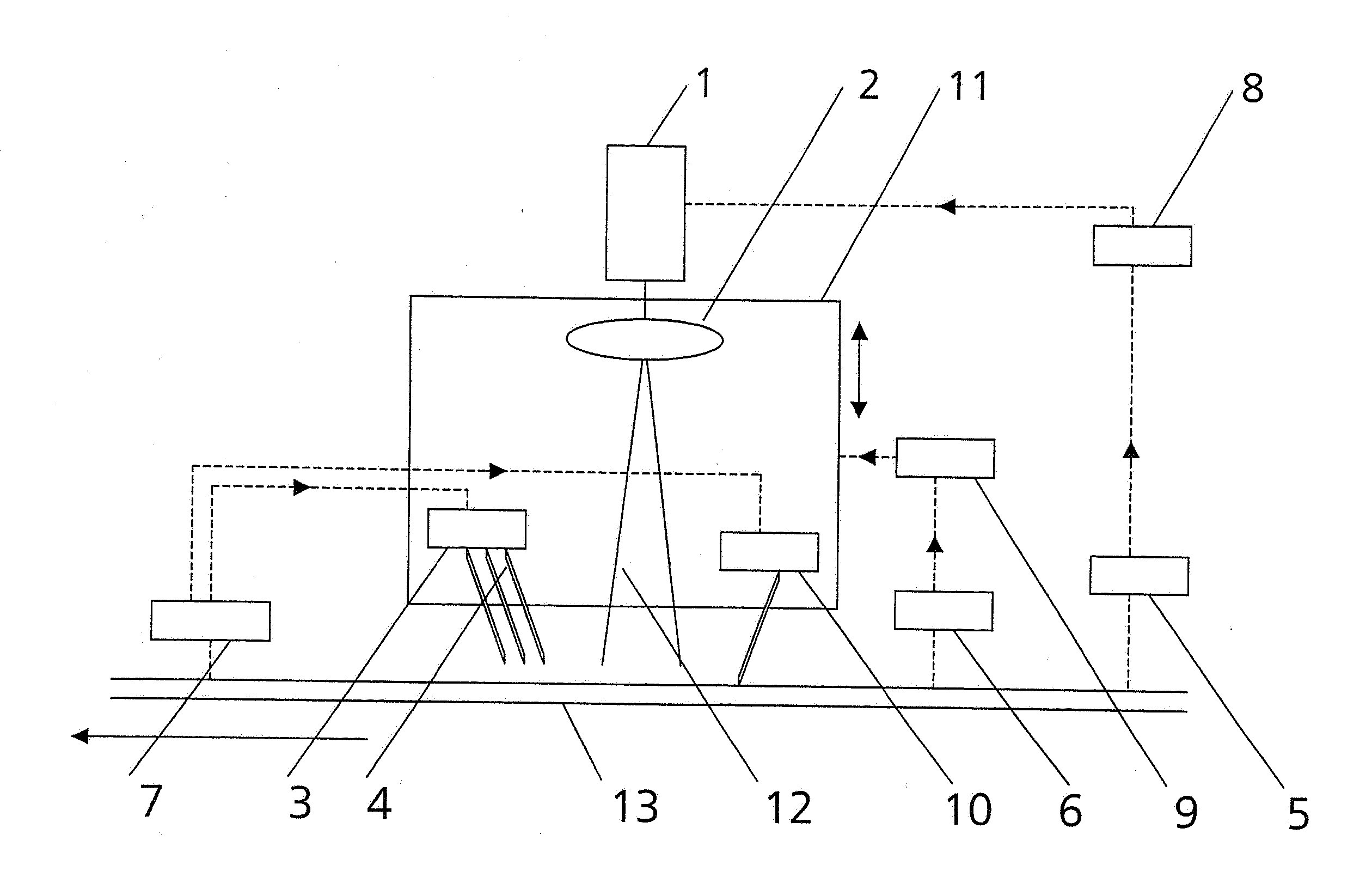
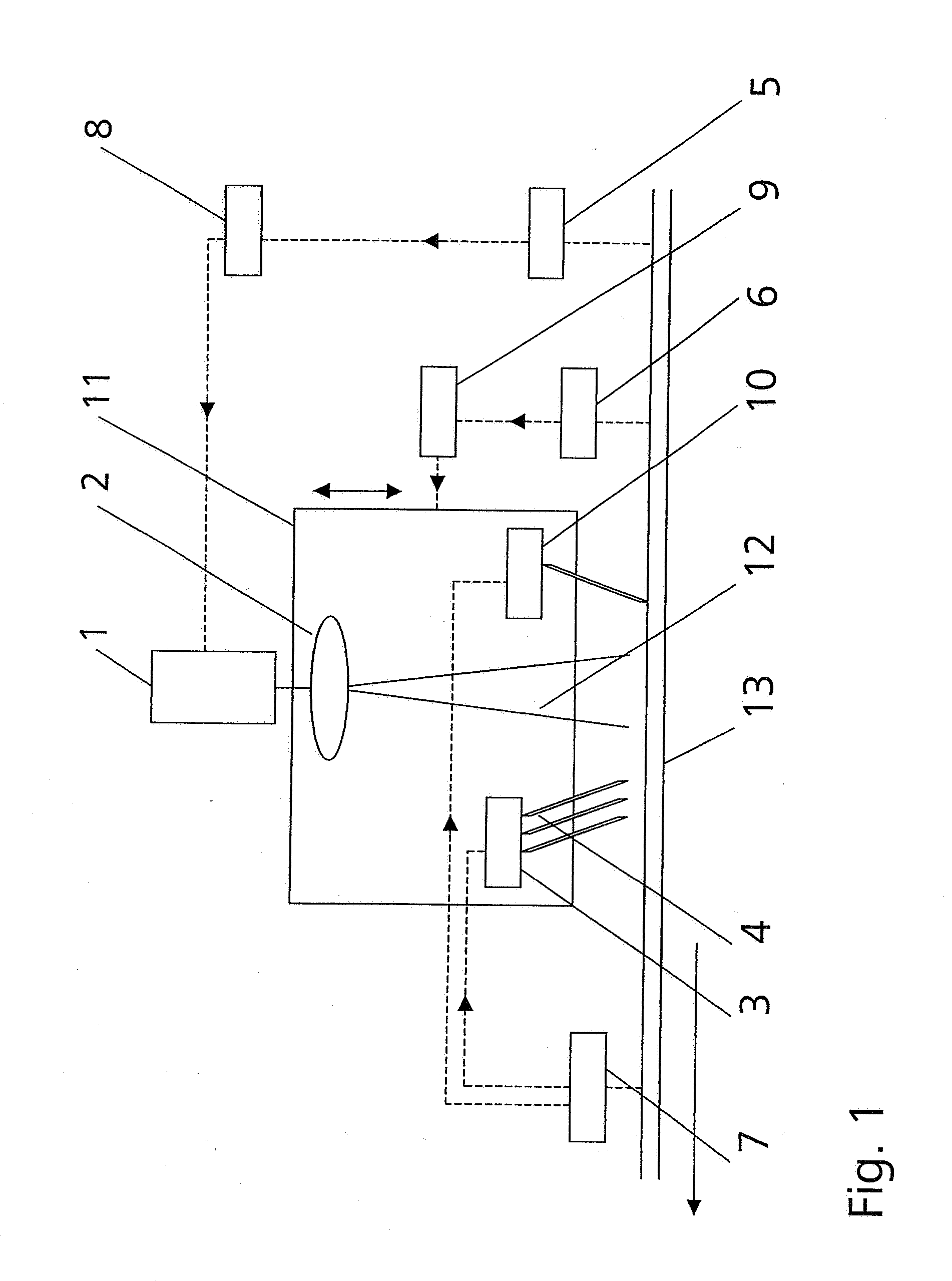
[0040]An apparatus according to the invention can basically be mounted at a bridge or a frame above the horizontal transporting device of a float glass installation. Two apparatuses which may share a temperature sensor 5 and a thickness sensor 6, as the case may be, are required to cut off both edges of a float glass ribbon 13 simultaneously.

[0041]As is shown in FIG. 1, an apparatus according to the invention basically comprises a laser 1, beam-shaping optics 2 which are arranged downstream of the laser 1 and which shape the emitted laser beam bundle 12 into a beam bundle with an elliptical cross section, a cooling arrangement 3 with a plurality of cooling nozzles 4 arranged one behind the other in a straight line, a temperature sensor 5 which measures in a noncontacting manner, e.g., an IR sensor, a thickness sensor 6 which measures in a noncontacting manner, e.g., an ultrasonic sensor, a crack detector 7, a control device 8 by which the laser output is controlled as a function of ...


PUM


Abstract

A method and apparatus for trimming the edges of a float glass ribbon whose thickness can vary between 0.4 mm and 24 mm in which a specific depth crack is generated for the respective thickness. The depth of the crack is actively influenced by energy introduced by means of a laser which is controlled as a function of the surface temperature of the float glass ribbon and by a subsequent cooling whose acting period is variable. To ensure a permanently reliable process, the severing crack and the thickness of the float glass ribbon are detected in order to initiate a new initial crack immediately in the event that the severing crack should break up and so that a cutting unit comprising the scribing device, the beam-shaping optics and the cooling nozzles is always at a constant vertical distance from the surface of the float glass ribbon. The method and apparatus are distinguished particularly by the fact that only a low laser power is required.

Description

CROSS-REFERENCE TO RELATED APPLICATION [0001]This application claims priority of German Application No. 10 2006 024 825.2, filed May 23, 2006, the complete disclosure of which is hereby incorporated by reference.BACKGROUND OF THE INVENTION[0002]a) Field of the Invention[0003]This invention is directed to a method and apparatus for trimming the edges of a float glass ribbon.[0004]b) Description of the Related Art[0005]U.S. Pat. No. 5,609,284 is one of the first patents to be published in which specific consideration is given to the correlation of process parameters with regard to a method for severing brittle flat material, particularly glass, by means of generating thermally induced stresses which lead to a crack of a specific depth.[0006]A CO2 laser (wavelength 10.6 μm) which is favorably absorbed by glass is preferably used in the method described in the above-cited patent. The parameters that are mentioned as having an influence on the crack depth δ which is crucial for the quali...

Claims


Application Information

Patent Timeline
Patent Type & Authority Applications(United States)
IPC IPC(8): F27B9/28F27D3/00F27D21/00F27D19/00
CPCC03B33/091C03B33/0235
Inventor ACKER, STEFANWEISSER, JUERGENEBERHARDT, GABRIELEULLMANN, RONNYKONDRATENKO, VLADIMIR STEPANOVICH
Owner JENOPTIK AUTOMATISIERUNGSTECHN
Why Eureka
Try Eureka