Circuit board
a circuit board and circuit technology, applied in the field of circuit boards, can solve the problems of difficult to reduce costs, and functions that cannot be easily changed, and achieve the effect of easy selection of functions to us
- Summary
- Abstract
- Description
- Claims
- Application Information
AI Technical Summary
Benefits of technology
Problems solved by technology
Method used
Image
Examples
first embodiment
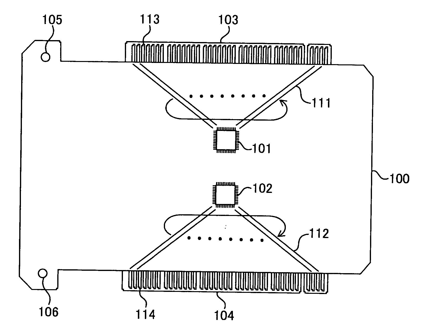
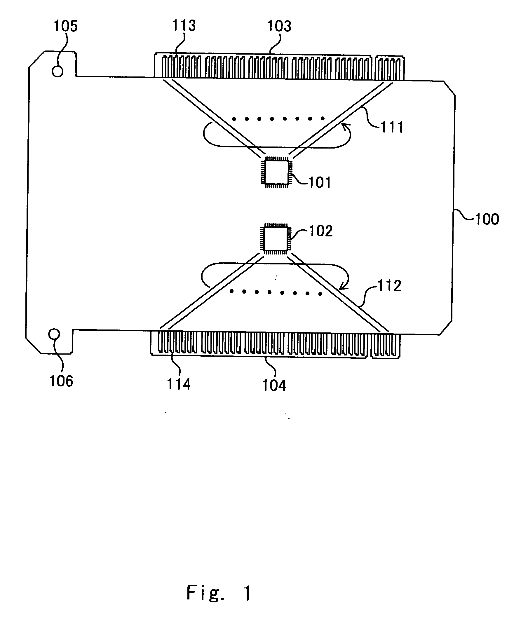
[0029]An adopter card according to the present invention is described hereinafter in detail with reference to FIG. 1. FIG. 1 is a plan pattern view showing a structure example of the adopter card. As shown in FIG. 1, an adopter card 100 includes a first LSI 101, second LSI 102, first male connector 103, second male connector 104, screw holes 105 and 106.
[0030]The LSIs 101 and 102 are examples of a circuit device performing predetermined functions that are placed over the principle surface of the rectangle adopter card 100 and fixed near the center of the principle surface. The LSIs 101 and 102 are connected to wiring groups 111 and 112 respectively by each terminal for PCI (not shown) and also connected to metal terminals 113 and 114 of the male connectors 103 and 104 via the wiring groups 111 and 112.
[0031]The male connectors 103 and 104 are placed to long sides of the rectangle adaptor card 100, being symmetric each other with respect to a center line (symmetry axis) running throu...
second embodiment
[0047]In a second embodiment, two LSIs are mounted as with the first embodiment. However in an adopter card of the second embodiment, the LSIs 101 and 102 each functions as a USB controller and IEEE 1394 controller.
[0048]The configuration of the adopter card according to the second embodiment is described hereinafter in detail with reference to FIGS. 4 and 5. FIG. 4 is a plan pattern view showing a structure example of the adopter card according to the second embodiment. Hereinafter, like parts in the adapter card 100 of the first embodiment are marked throughout the specification with the same reference numerals with description omitted.
[0049]As shown in FIG. 4, the adapter card 300 includes a first device side connector 301 and a second device side connector 302 in addition to the configuration of the first embodiment. The device side connector 301 functions as a USB connector corresponding to the LSI 101. On the other hand, the device side connector 302 functions as an IEEE 1394 ...
third embodiment
[0062]In a third embodiment, an adapter card is described in which two LSIs perform particular functions as with the second embodiment but the LSIs perform the same function having different characteristics. Specifically, in the adapter card of the third embodiment, the LSIs 101 and 102 respectively function as a first data link layer controller and a second data link layer controller in the IEEE 1394.
[0063]The configuration of the adapter card according to the third embodiment is described hereinafter in detail with reference to FIGS. 7 and 8. FIG. 7 is a plan pattern view showing a structure example of an adapter card according to the third embodiment. In the description that follows, like parts as the adapter card 300 of the second embodiment are marked throughout the specification with the same reference numerals with their description omitted. As shown in FIG. 7, the adapter card 400 includes a device side connector 401, third LSI 402 and bus switching circuit 403 in addition t...
PUM
 Abstract
Description
Claims
Application Information
 - R&D
- Intellectual Property
- Life Sciences
- Materials
- Tech Scout
- Unparalleled Data Quality
- Higher Quality Content
- 60% Fewer Hallucinations
Browse by: Latest US Patents, China's latest patents, Technical Efficacy Thesaurus, Application Domain, Technology Topic, Popular Technical Reports.
© 2025 PatSnap. All rights reserved.Legal|Privacy policy|Modern Slavery Act Transparency Statement|Sitemap|About US| Contact US: help@patsnap.com


