Shutter slat end retention system

Active Publication Date: 2007-12-06
QUALITAS MFG
View PDF36 Cites 4 Cited by
  • Summary
  • Abstract
  • Description
  • Claims
  • Application Information

AI Technical Summary

Benefits of technology

[0016]The fastener may have a second shaft, which is smooth. Additionally, the fastener may have a lip, where the lip is located between the

Problems solved by technology

These special tracks may be undesirable because they may require special channels that limit the amount of horizontal travel, or “slip” (travel in the plane of the shutter that is perpendicular the direction of opening and closing of the shutter, which is usually vertical) the shutter curtain has in its operation.
This limited amount of slip increases the pressure on the fastening system that holds the guides to the structure caused by catenary forces established when the curtain is put under load.
Another drawback of the channels of these special tracks is that they may increase the necessary sophistication of the overall shutter design to allow for funneling the end retention system into the channels and for keeping the shutter curtain correctly aligned.
One problem that may arise with this type of end retention system is that a moment may be created in the screw (fastener), because it extends from the curtain profile and may act as a lever.
If the end retention system happens to be out of line or catches on the retention fins of the side tracks or something else, the system can be bent or torn out and can cause a malfunction of the operation of the shutter curtain.
To increase the desired slip in a system using specia

Method used


Image

  • Shutter slat end retention system
  • Shutter slat end retention system
  • Shutter slat end retention system

Examples


Embodiment Construction

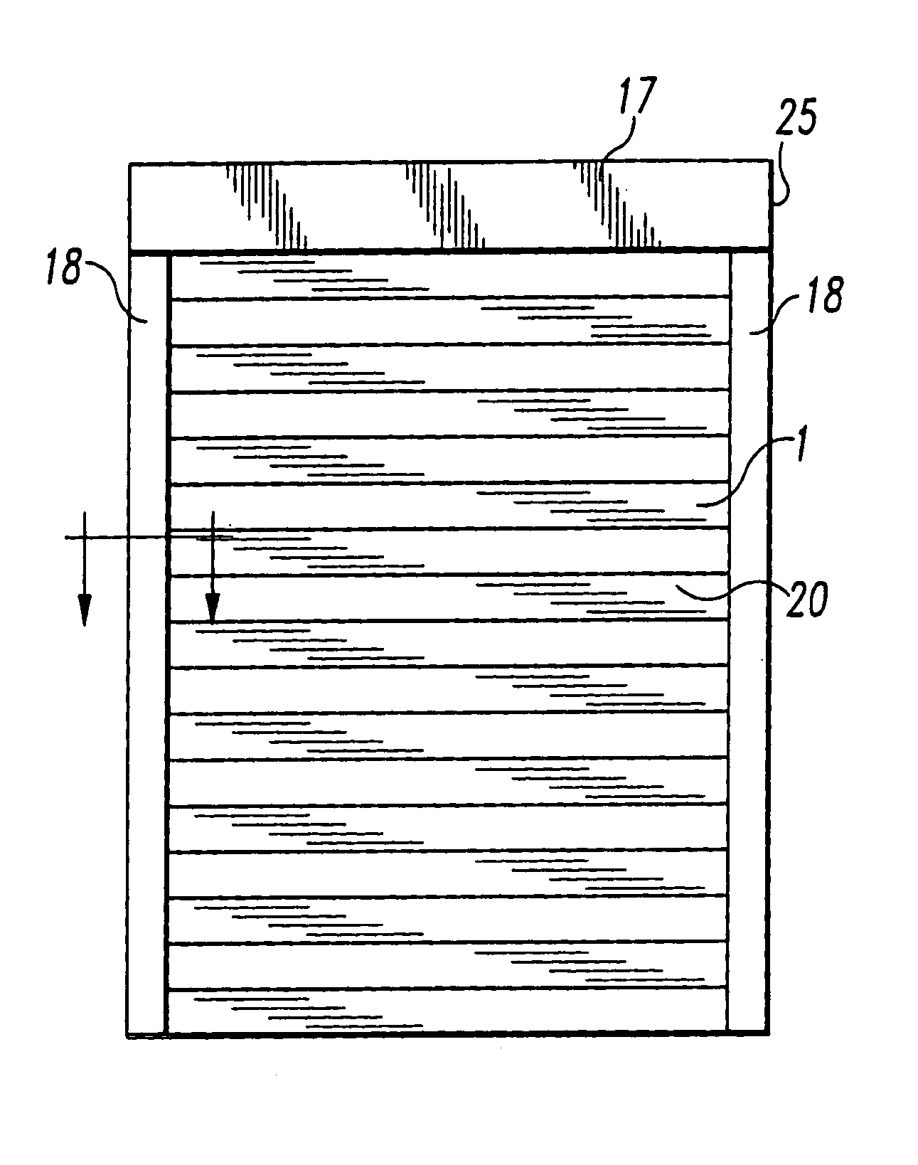
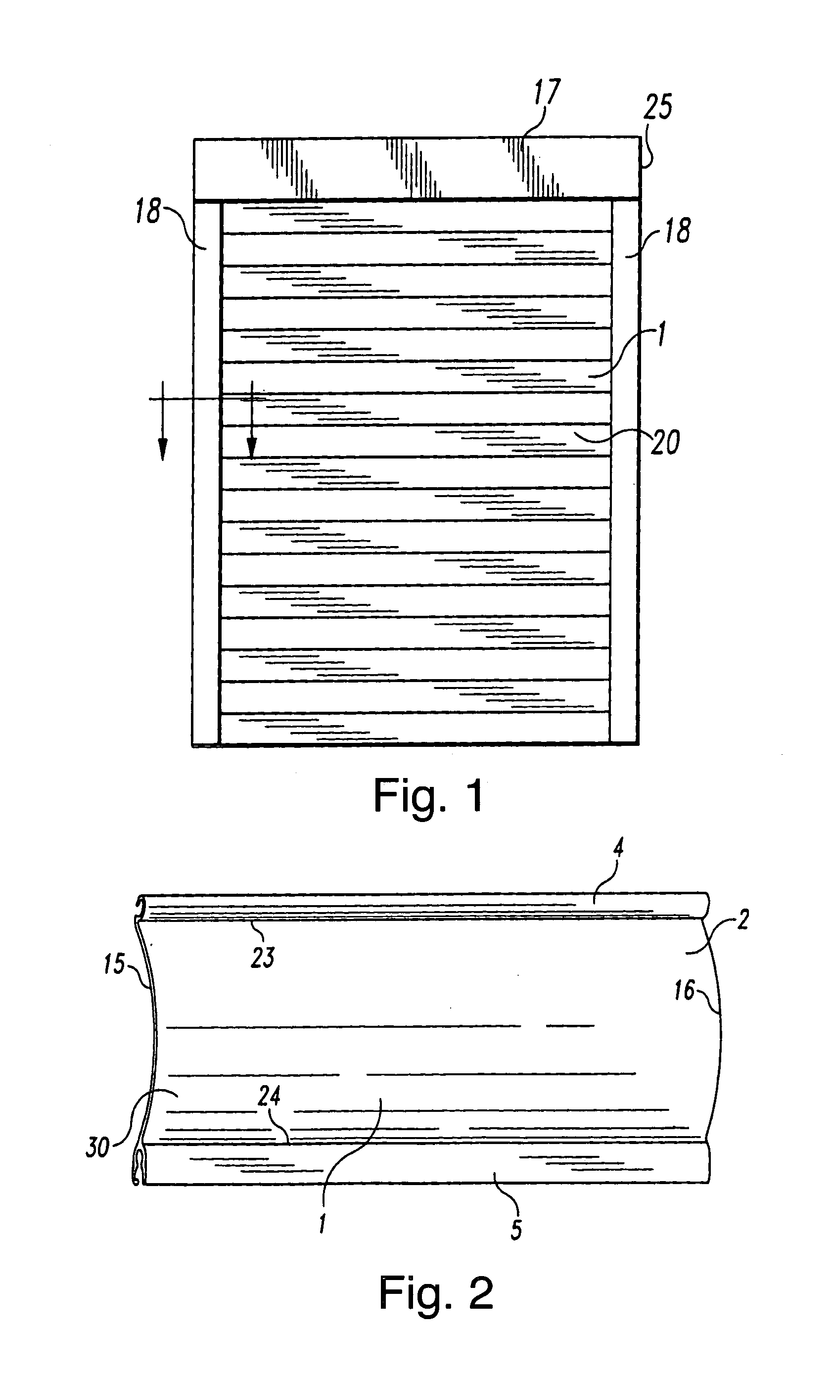
[0034]FIG. 1 shows an illustrative roller shutter 20 (shutter curtain) installed on a building aperture 25, such as a window or a door. The building aperture 25 may be further equipped with a shutter casing 17 and guides 18. The guides 18 may be located on opposite lateral edges of the building aperture 25. The roller shutter 20 may be rolled up for storage within the shutter casing 17.

[0035]FIG. 2 shows an illustrative shutter slat 1, a plurality of which is shown in the roller shutter 20 in FIG. 1. Illustratively, the shutter slat 1 is an elongated body of single-ply extruded aluminum having a first end 15 and a second end 16, a body portion 30 bounded by an upper edge 23 and a lower edge 24, and an engaging track 4 and a receptacle track 5. The first and second ends 15 and 16 of the shutter slat 1 may be adjacent the guides 18 shown in FIG. 1. A retention system 3, as shown in FIG. 10, may provide for a secure alignment of the ends 15 and 16 with the guides 18.

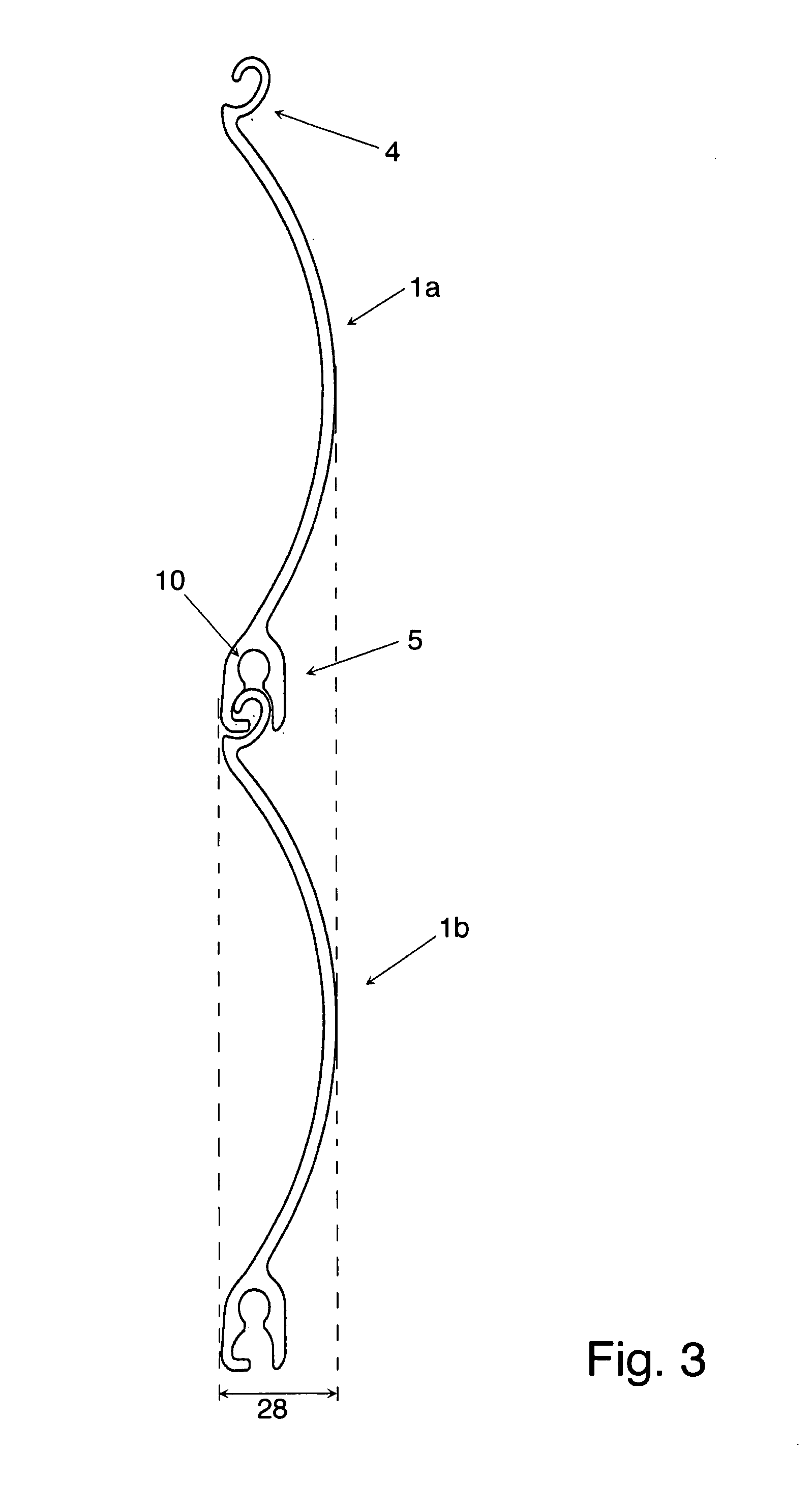
[0036]FIG. 3 is a d...


PUM


Abstract

An end retention system for a rolling shutter system is provided. The end retention system comprises a fastener that has a head and a shaft, and a washer that has an outer diameter and an aperture having an inner diameter. The inner diameter of the aperture of the washer is at least twice the diameter of the shaft of the fastener. The shaft is configured for insertion into a screw boss receptacle of a shutter slat. The end retention system may also comprise a guide track that has retention fins spaced apart a distance that is less than the outer diameter of the washer. The guide may include a channel that partially bounded by the retention fins. The channel may have a width that is greater than the outer diameter of the washer. The washer is located in the channel, and is retained near the slat by the head of the fastener.

Description

BACKGROUND OF THE INVENTION[0001]The present invention relates to shutters and in particular to shutters of the roller type. It furthermore relates to an end retention system for use with a slat of a rolling shutter.DESCRIPTION OF THE RELATED ART[0002]Conventional roller shutters are designed to provide security from break-ins and protection from storms. Because such protection and security may not always be necessary or desired, such as during the day when a retail store is open for business or during fine weather when a homeowner wishes to open windows, roller shutters are designed to be retractable into a casing in which they are stored. To facilitate compact storage, the rigid shutter slats that are designed to resist hurricane winds and burglars must be capable of conforming to a roll.[0003]The slats of roller shutters are commonly aligned and held in place by guides, or side tracks. End retention systems are known for use in rolling shutters and doors to keep the shutter curta...

Claims


Application Information

Patent Timeline
IPC IPC(8): E06B9/08
CPCE06B9/581E06B9/15E06B2009/1588
Inventor MILLER, JAMES V.
Owner QUALITAS MFG
Why Eureka
Try Eureka