Power storage device and mobile electronic device having the same

a technology of power storage device and mobile electronic device, which is applied in electromagnetic wave system, instruments, transportation and packaging, etc., can solve the problems of reducing the power consumption of coping with the operating time, affecting the operation of load, and affecting the durability of batteries, so as to reduce the power consumption of batteries and ensure the operation of load for a long time

Active Publication Date: 2007-12-06
SEMICON ENERGY LAB CO LTD
View PDF20 Cites 117 Cited by
  • Summary
  • Abstract
  • Description
  • Claims
  • Application Information

AI Technical Summary

Benefits of technology

[0007]However, the frequency of usage of mobile electronic devices such as portable telephones and digital video cameras has risen steadily, and there is a limit to improving the durability of batteries and reducing the power consumption for coping with the operating time. Further, for charging batteries which are a power source built in portable telephones, digital video cameras, and the like, there have not been any methods other than charging from a household AC power supply through an AC adaptor or from a commercially available primary battery. Therefore, charging has been troublesome for users, and it has been necessary for users to take an AC adaptor or a primary battery which is a power supply means with them when they are moving about outdoors, which is burdensome.
[0010]Therefore, an object of the invention is to provide a power storage device for regularly supplying power to a mobile electronic device and provide a mobile electronic device having the power storage device, in which charging of a battery by a power feeder which is a power supply means is simplified; in which there is no possibility of malfunctions which could occur if a relay terminal for directly connecting the battery and the power supply means is provided, and no possibility of damage to the relay terminal itself; and in which power consumption of the battery along with the usage for a long time can be mitigated.
[0024]The power storage device of the invention has an antenna circuit. Therefore, there is no need to provide a relay terminal as a portion which conducts electricity to a battery, and there is no possibility of malfunctions occurring due to breakdown or defects of the relay terminal, so that the battery can be charged by using radio signals.
[0025]In addition to the above advantages obtained by providing the battery in the power storage device of the invention, a switch circuit is provided in the power supply control circuit which supplies power to the load, so that the power supply to the load is regularly controlled. By controlling the power supply to the load using the switch circuit provided in the power supply control circuit, the power supply to the load can be conducted intermittently. Therefore, reduction in power consumption of the battery can be achieved, and further, the load can be operated for a long time even when there is no power supply via radio signals.

Problems solved by technology

However, the frequency of usage of mobile electronic devices such as portable telephones and digital video cameras has risen steadily, and there is a limit to improving the durability of batteries and reducing the power consumption for coping with the operating time.
Further, for charging batteries which are a power source built in portable telephones, digital video cameras, and the like, there have not been any methods other than charging from a household AC power supply through an AC adaptor or from a commercially available primary battery.
Therefore, charging has been troublesome for users, and it has been necessary for users to take an AC adaptor or a primary battery which is a power supply means with them when they are moving about outdoors, which is burdensome.
Thus, there has been a problem in that malfunctions could occur when the relay terminal is damaged or defective.
In such a mobile electronic device, power consumption of the battery increases significantly when power is continuously and constantly supplied to the load from the battery, unlike the power supply from a fixed power source.
Therefore, there has been a problem in that the usage of the mobile electronic device for a long time is limited when a power supply to the battery cannot be secured.

Method used


Image

  • Power storage device and mobile electronic device having the same
  • Power storage device and mobile electronic device having the same
  • Power storage device and mobile electronic device having the same

Examples


embodiment mode 1

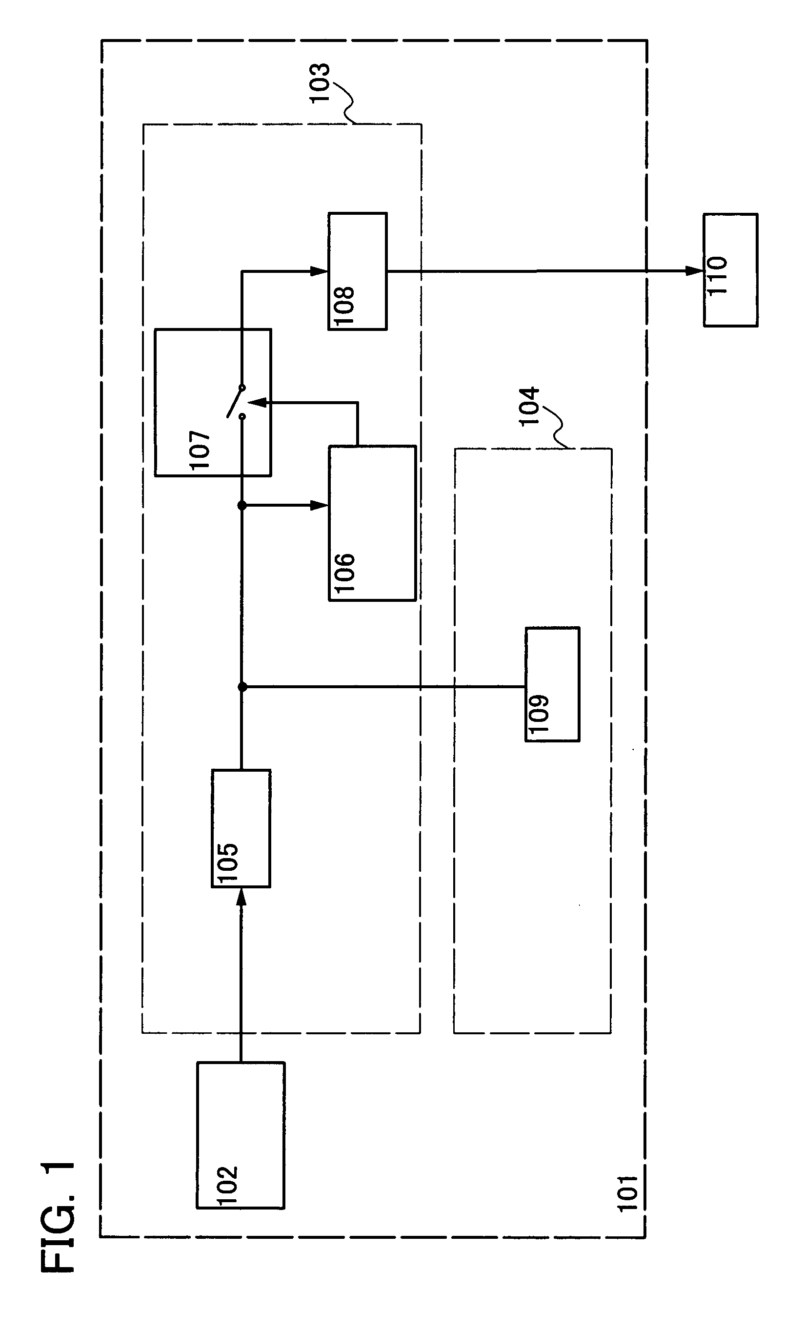
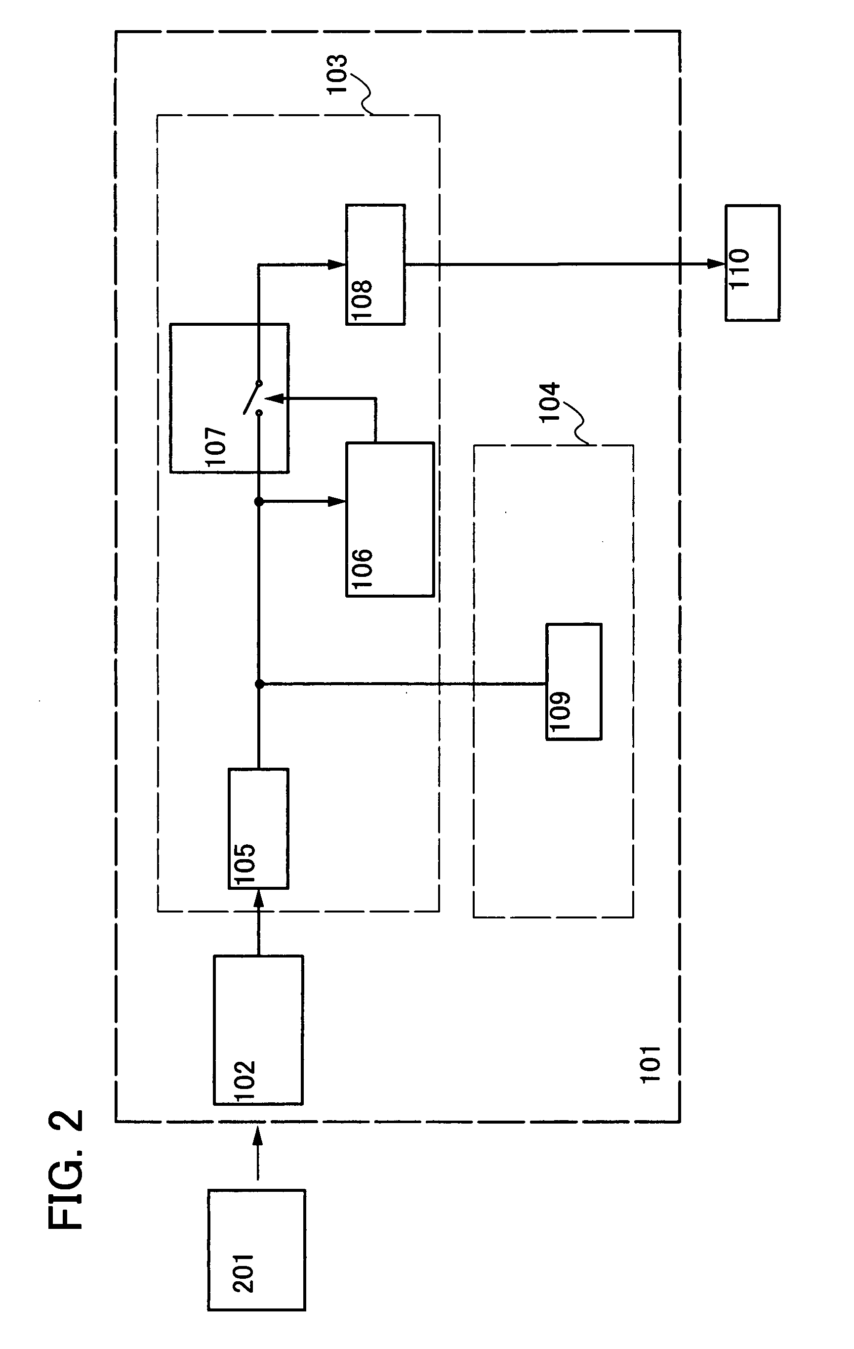
[0062]Structural examples of a power storage device of the invention will be described with reference to the block diagrams of FIGS. 1 and 2.

[0063]A power storage device 101 in FIG. 1 includes an antenna circuit 102, a power supply control circuit 103, and a battery portion 104. The power supply control circuit 103 includes a rectifier circuit 105, a low-frequency-signal generating circuit 106, a switch circuit 107, and a power supply circuit 108. The battery portion 104 includes a battery 109. Note that the power supply circuit 108 in the power supply control circuit 103 outputs power to a load 110 which is located outside the power storage device 101.

[0064]Note that the structure of the load 110 in FIG. 1 differs from mobile electronic device to mobile electronic device. For example, as an example of a load in a portable telephone or a digital video camera, a display portion, an integrated circuit portion, and the like can be given. As an example of a load in a temperature sensor,...

embodiment mode 2

[0094]This embodiment mode will describe a structure where the power storage device shown in Embodiment Mode 1 further includes a control circuit which selects one of the power from the antenna circuit and the power from the battery to be supplied to the power supply circuit in the power supply control circuit, with reference to the drawings. Note that in the drawings used in this embodiment mode, parts that are the same as those in Embodiment Mode 1 are denoted by the same reference numerals as those in Embodiment Mode 1.

[0095]One structural example of the power storage device of the invention in accordance with this embodiment mode will be described with reference to the block diagrams of FIGS. 13 and 14.

[0096]The power storage device 101 in FIG. 13 includes an antenna circuit 102, a power supply control circuit 103, and a battery portion 104. The power supply control circuit 103 includes a rectifier circuit 105, a control circuit 1601, a low-frequency-signal generating circuit 10...

embodiment mode 3

[0121]This embodiment mode will describe a structure where a booster antenna circuit (hereinafter referred to as a booster antenna) is provided in the power storage device shown in Embodiment Mode 1, with reference to the drawings. Note that in the drawings used in this embodiment mode, parts that are the same as those in Embodiment Mode 1 are denoted by the same reference numerals as those in Embodiment Mode 1.

[0122]Note that “booster antenna” as referred to in this embodiment mode means an antenna having a larger size than the antenna provided in the power storage device which receives radio signals from a power feeder. The booster antenna refers to an antenna which can efficiently transmit signals supplied from a power feeder to a target power receiving device, by resonating the signals from the power feeder at a particular frequency band and magnetically coupling the antenna circuit provided in the power receiving device with the booster antenna itself. Since the booster antenna...


PUM


Abstract

To provide a power storage device for regularly supplying power to a mobile electronic device, in which charging of a battery by a power feeder can be simplified and even when power stored in the battery is not enough, power can be regularly supplied to the mobile electronic device. The mobile electronic device includes an antenna circuit which receives power supply via radio signals, a battery which stores power, and a power supply control circuit which includes a switch circuit for intermittently supplying power to a load. Power supply to the load is intermittently controlled by controlling the switch circuit, which is provided in the power supply control circuit for controlling the supply of power stored in the battery, using a signal from a low-frequency-signal generating circuit.

Description

BACKGROUND OF THE INVENTION[0001]1. Field of the Invention[0002]The present invention relates to power storage devices. In particular, the invention relates to a power storage device which stores power through reception of radio signals.[0003]Note that “power storage device” as referred to in this specification means devices in general which store power through reception of radio signals from an external electric power supply device (a power feeder).[0004]2. Description of the Related Art[0005]Various electronic devices are coming into wide use and a wide variety of devices are on the market. In particular, in recent years, the spread of portable electronic devices has been marked. As an example, portable telephones, digital video cameras, and the like have become very convenient, having display portions with high definition, batteries that are more durable, and low power consumption. A portable electronic device has a built-in battery which is a power storage means. Thus, a power s...

Claims


Application Information

Patent Timeline
Patent Type & Authority Applications(United States)
IPC IPC(8): H02J7/00
CPCH02J17/00H02J7/0052H02J50/12H02J50/20H02J50/402H02J7/0068H02J50/40H02J7/00
Inventor KOYAMA, JUN
Owner SEMICON ENERGY LAB CO LTD
Why Eureka
Try Eureka