Determining if an image is blurred

a technology of blurred images and blurry images, applied in image analysis, visual presentation, image enhancement, etc., can solve the problems of enormous volume of processing, and achieve the effect of efficient determination of blurry images

Inactive Publication Date: 2007-12-06
SEIKO EPSON CORP
View PDF6 Cites 18 Cited by
  • Summary
  • Abstract
  • Description
  • Claims
  • Application Information

AI Technical Summary

Benefits of technology

[0029]Whether or not a human face in a photographic image is distinct is a factor having an appreciable effect on the determination by the user as to whether the overall image is blurred. According to the aspect described above, a specific pixel can be selected from among pixels in a thumbnail image which correspond to a region representing a human face in an image of photographic image data. Specifically, according to this aspect, processing is carried out on a region of the image with significant effect on the determination as to whether the overall image is blurred. Consequently, determinations of blurriness can be made efficiently.

Problems solved by technology

However, since the above technology requires that calculations be performed for each pixel in the image data, necessitating an enormous volume of processing.

Method used


Image

  • Determining if an image is blurred
  • Determining if an image is blurred
  • Determining if an image is blurred

Examples


embodiment 1

A. Embodiment 1

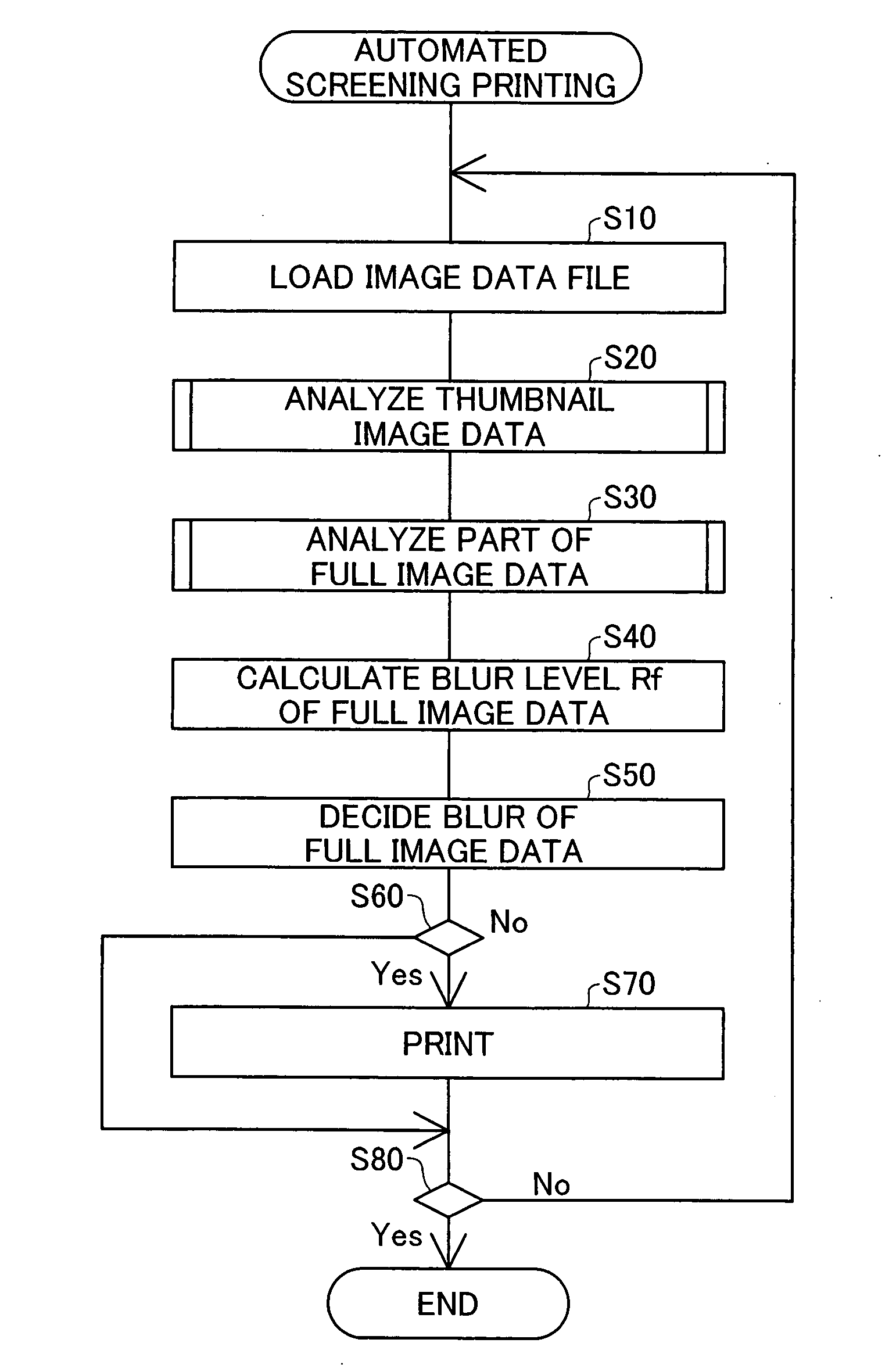
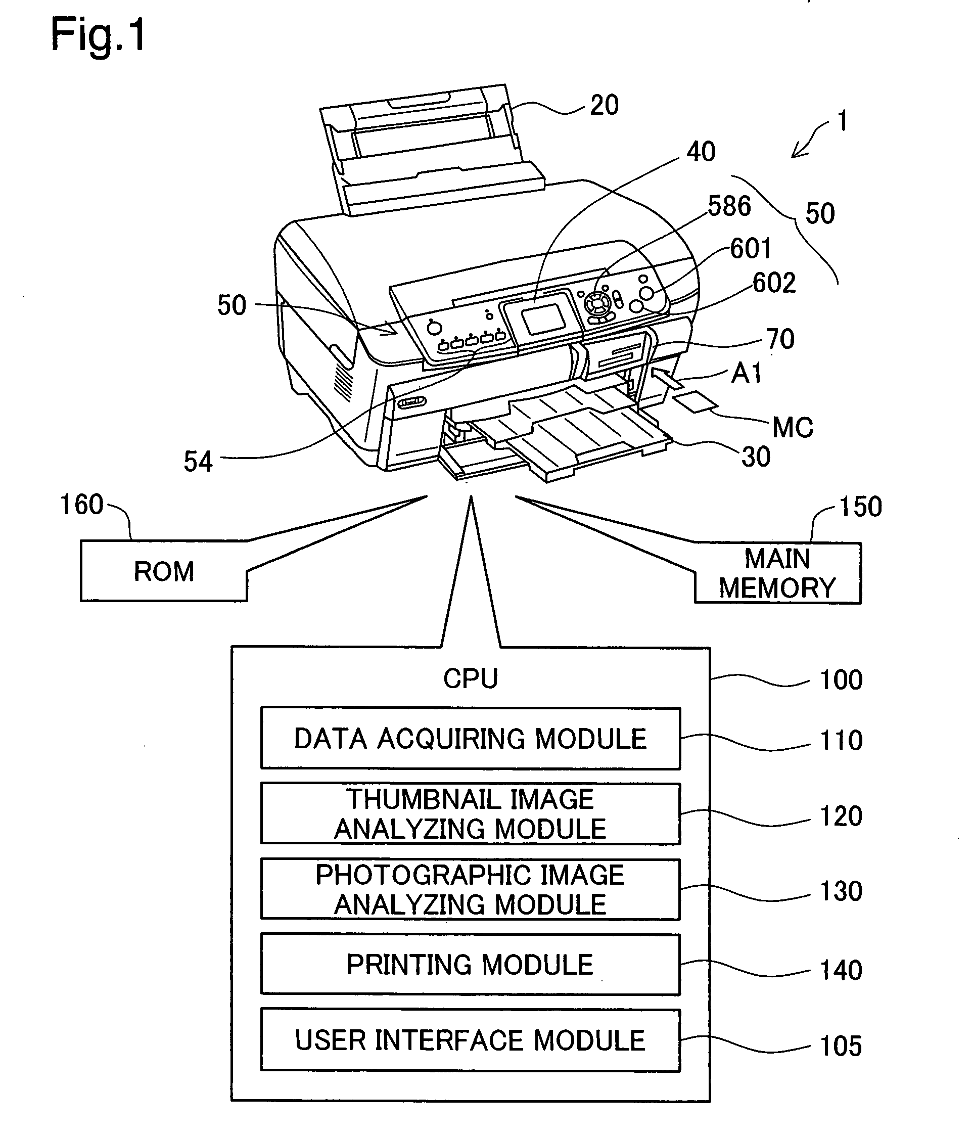
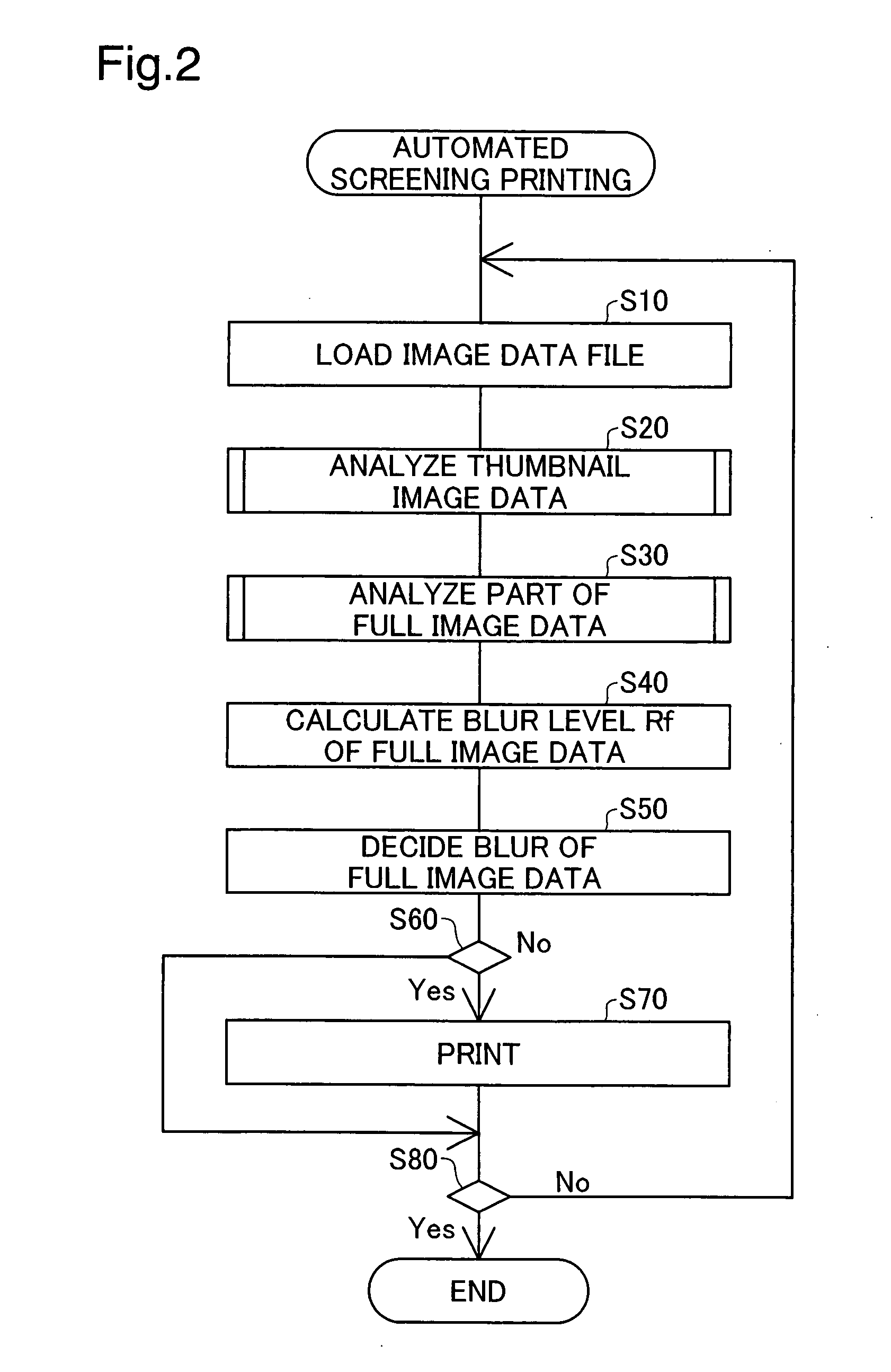
[0045]FIG. 1 is a perspective view of the present invention in the embodiment of a printer 1. The printer 1 is able to carry out printing independently on the basis of an image data file stored on a recording medium, without the printer being connected to an external computer. This printer 1 includes a print head (not shown) that prints by ejecting ink drops; an auto sheet feed 20 for feeding the printing paper; a paper discharge tray 30 for receiving printing paper on which images have been imprinted; a liquid crystal display 40; a button group 50 for performing various operations; a card slot 70 for reading data from an inserted memory card; a CPU 100; a main memory 150; and a ROM 160. In FIG. 1, the CPU 100, the main memory 150, the ROM 160 are depicted to the outside of the printer as a aid to description.

[0046]A memory card MC such as a Compact Flash™ card, SD card, miniSD card, memory stick, smart media card, or the like can be inserted into the card slot 70 dir...

embodiment 2

B. Embodiment 2

[0092]In Embodiment 1, there is a one-to-one correspondence between one pixel of a thumbnail image, and a block region of the full image (see FIGS. 4 and 5). Edge width We is calculated on the basis of luminance at pixel positions in a target region Apt and a neighboring region Apn (see FIG. 8). In Embodiment 2, the size of block regions of the full image is constant and not dependent on the size of the full image or the thumbnail image. For this reason correspondence between one pixel of a thumbnail image and a block region of the full image is not limited to one-to-one correspondence. Also, edge width We is determined on the basis of a DCT coefficient of block regions. In other respects, Embodiment 2 is the same as Embodiment 1.

[0093]FIG. 9 is a diagram depicting DCT coefficients for an image of a target region in which image data is stored in JPEG format. The JPEG format image data stores coefficients (DCT coefficients) F00-F77 representing frequency components of ...

modified example 1

C1. Modified Example 1

[0114]In Embodiment 1, luminance of each pixel is employed as the criterion for edge pixel (specific pixel) selection. However, during specific pixel selection, the specific pixel can be selected on the basis of some other pixel tone value. For example, the specific pixel can be selected on the basis of a tone value representing intensity of red, green, or blue, instead of luminance.


PUM


Abstract

A technology for making determinations as to whether the image of an image data file is blurred, with low processing load, is provided. First, photographic image data PID containing pixel color information, as well as thumbnail image data for the photographic image data, are prepared. A specific pixel is then selected from among the pixels of the thumbnail image data. Specifically, on the basis of data of a pixel under examination and data of a pixel neighboring the pixel under examination, it is determined whether the pixel under examination should be designated as the specific pixel. Then, for a specific region Ape which is a region constituting part of the photographic image data PID and which corresponds to the specific pixel of the thumbnail image data, analysis of the photographic image PID is carried out, and a localized blur level that represents indistinctness of the image in the specific region Ape is calculated. Subsequently, in the event that the localized blur level of the specific region Ape contained in the photographic image data PID meets a prescribed condition, it is determined that the image of the photographic image data PID is blurred.

Description

BACKGROUND[0001]1. Technical Field[0002]The present invention relates to technology for determining the extent of blur in the image of an image data file.[0003]2. Related Art[0004]Technologies employing a process such as the following to determine whether an image is blurred have been known to date. Specifically, the differences in brightness fx, fy between a target pixel in an image and pixels neighboring the target pixel in the X direction and the Y direction are determined, and the square root g (x, y) of the sum of squares is calculated. The average value of g (x, y) for all pixels in the image is then calculated by way of a “sharpness level SL.” On the basis of the magnitude of SL, a decision is made as to whether the image is blurred.[0005]However, since the above technology requires that calculations be performed for each pixel in the image data, necessitating an enormous volume of processing.[0006]With a view to addressing the above issue, an advantage of some aspects of the...

Claims


Application Information

Patent Timeline
Patent Type & Authority Applications(United States)
IPC IPC(8): G06K15/00
CPCG06K15/02G06T7/0085G06T7/0095G06K15/1822H04N1/00175H04N1/00188G06K15/186H04N1/00132G06T7/13G06T7/168
Inventor MATSUZAKA, KENJI
Owner SEIKO EPSON CORP
Why Eureka
Try Eureka