

Liquid crystal display apparatus
a technology of liquid crystal display and display apparatus, which is applied in the direction of lighting and heating apparatus, lighting device details, instruments, etc., can solve the problems of mechanical and thermal stress on the display apparatus, and achieve the effect of eliminating the failure caused by deformation of the optical sh
- Summary
- Abstract
- Description
- Claims
- Application Information
AI Technical Summary
Benefits of technology
Problems solved by technology
Method used
Image

Examples
first embodiment
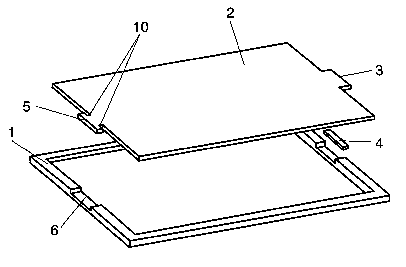
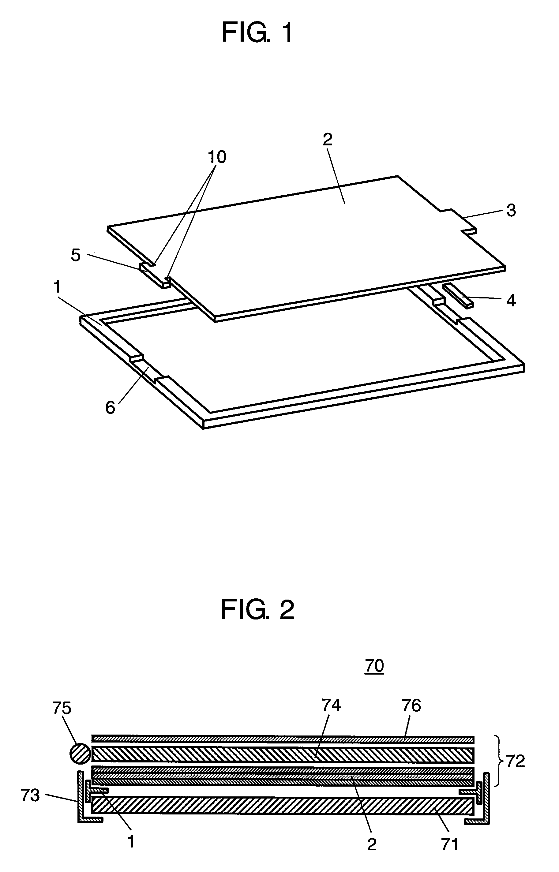
[0040]FIG. 1 is a perspective view of a liquid crystal display apparatus in the first exemplary embodiment of the present invention. Only resin frame 1, optical sheet 2, and double-sided tape 4 are illustrated in FIG. 1; no liquid crystal display, light guide plate, reflection sheet, tubular light source, metal bezel, or driving circuit board are shown. As shown in FIG. 1, in the liquid crystal display apparatus in the first exemplary embodiment, first fixing portion 3 provided at one side of optical sheet 2 is secured onto resin frame 1 with double-sided tape 4. Second fixing portion 5, provided at the side opposite the side on which first fixing portion 3 is provided, is not secured with double-sided tape, but fitted to concavity 6 created at resin frame 1 at a part corresponding to second fixing portion 5 so as to attach optical sheet 2 to resin frame 1. Optical sheet 2 has rectangular notch 10.
[0041]FIG. 2 is a sectional view illustrating the structure of liquid crystal display ...
second embodiment
[0056]A liquid crystal display apparatus in the second embodiment of the present invention is described with reference to drawings. Components which are the same as those in the first exemplary embodiment are given the same reference marks to avoid redundancy. FIG. 8 is a fragmentary plan view illustrating the details of liquid crystal display apparatus 70 which has L-shaped protrusions in positioning areas 111 and 112 in the second embodiment. As shown in FIG. 8, liquid crystal display apparatus 70 in the second embodiment is characterized by the L-shaped protrusions in positioning areas 111 and 112 of second fixing portion 5 provided at optical sheet 2, and curved portions 121 and 122 processed on concavity 6 of resin frame 1 in a way such that to engage with the L-shaped protrusions.
[0057]The L-shaped protrusions of positioning areas 111 and 112 protruding from second fixing portion 5 and curved portions 121 and 122 of resin frame 1 corresponding to L-shaped protrusions are creat...
third embodiment
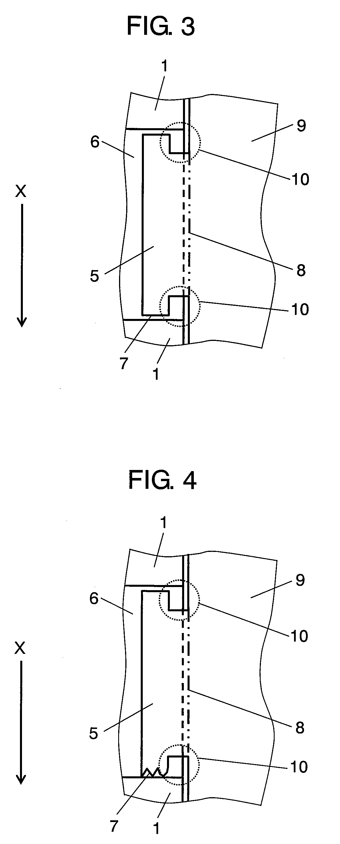
[0067]A liquid crystal display apparatus in the third embodiment of the present invention is described with reference to drawings. Components which are the same as those in the first embodiment are given the same reference marks to avoid redundancy. FIG. 11 is a fragmentary plan view illustrating the details of liquid crystal display apparatus 70 which has trapezoidal protrusions in positioning areas 131 and 132 in the third embodiment of the present invention. As shown in FIG. 11, liquid crystal display apparatus 70 in the third embodiment is characterized by its trapezoidal protrusions of positioning areas 131 and 132 protruding from second fixing portion 5 formed on optical sheet 2, and curved portions of concavity 16 in resin frame 1 processed in a way such that to contact the trapezoidal protrusions of positioning areas 131 and 132 in second fixing portion 5.
[0068]With this structure, if a mechanical stress is applied in direction X in the state shown in FIG. 11, the stress is ...
PUM
 Abstract
Description
Claims
Application Information