Zoom lens and image capture apparatus
- Summary
- Abstract
- Description
- Claims
- Application Information
AI Technical Summary
Benefits of technology
Problems solved by technology
Method used
Image

Examples
first embodiment
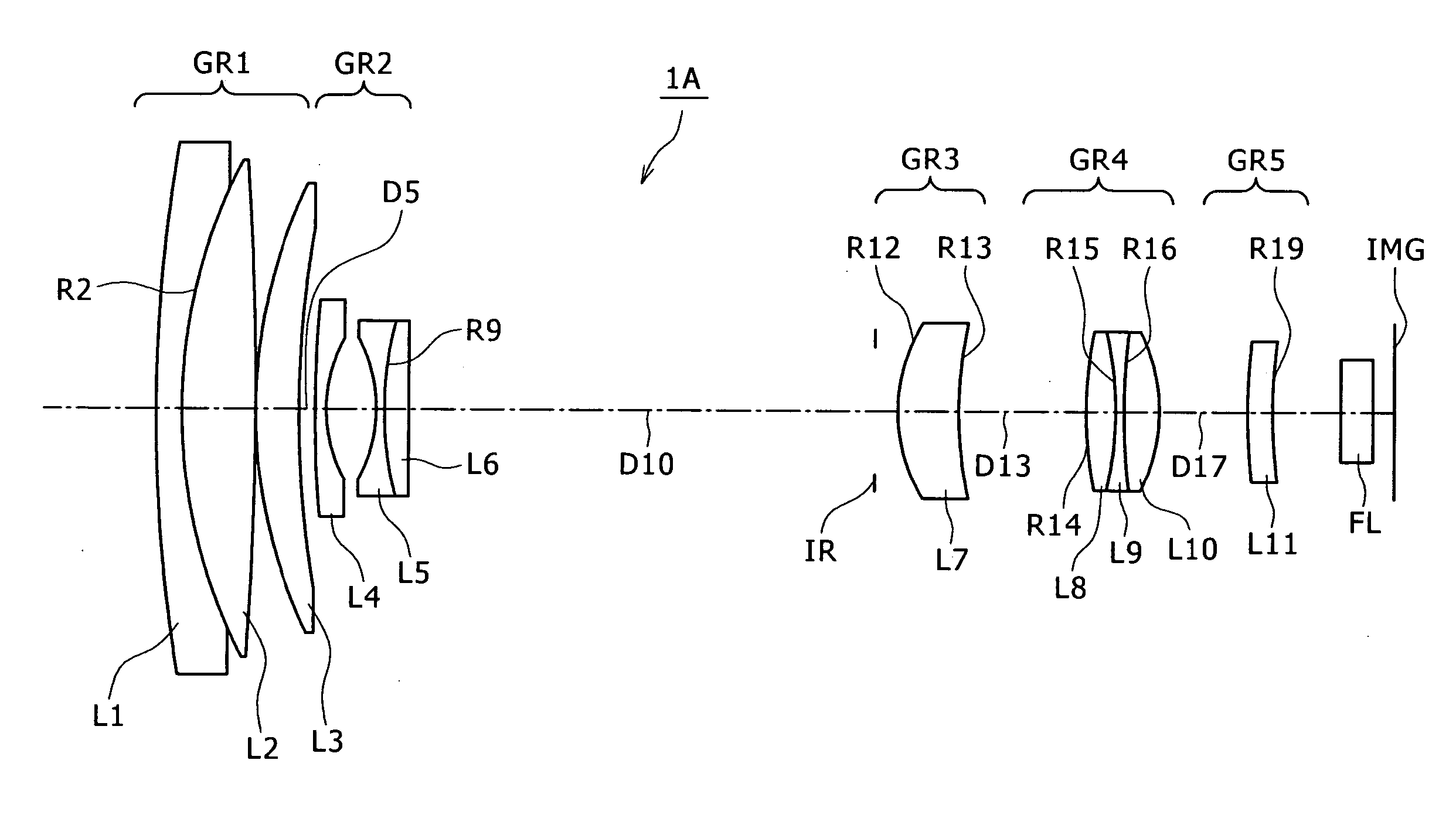
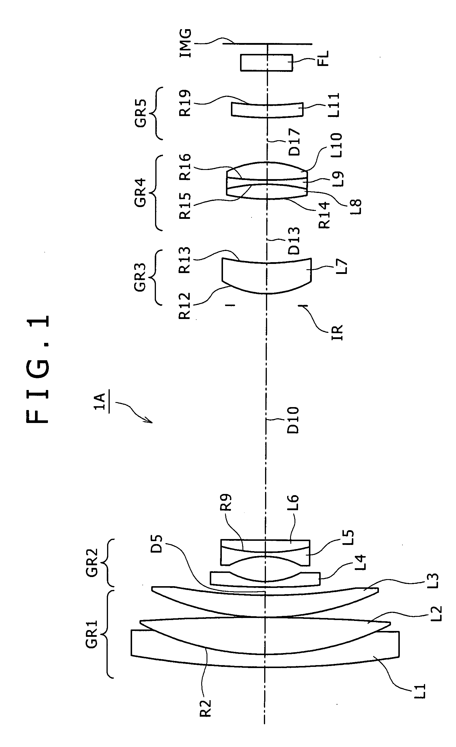
[0063] The zoom lens 1A includes eleven lenses in total, as shown in FIG. 1.
[0064] The first lens group GR1 has the positive refractive power on the whole, and is configured with three lenses L1, L2 and L3. It is noted that with respect to the lenses L1 and L2, a concave surface and a convex surface that are respectively on an image-plane side of the lens L1 and an object side of the lens L2 and have the same radius of curvature are cemented together into a cemented lens having a cemented surface R2.
[0065] The second lens group GR2 has the negative refractive power on the whole, and is configured with three lenses L4, L5 and L6. The second lens group GR2 is movable in position for movement in the direction of the optical axis for providing mainly zooming. It is noted that with respect to the lenses L5 and L6, a concave surface and a convex surface that are respectively on an image-plane side of the lens L5 and an object side of the lens L6 and have the same radius of curvature are...
embodiment 1
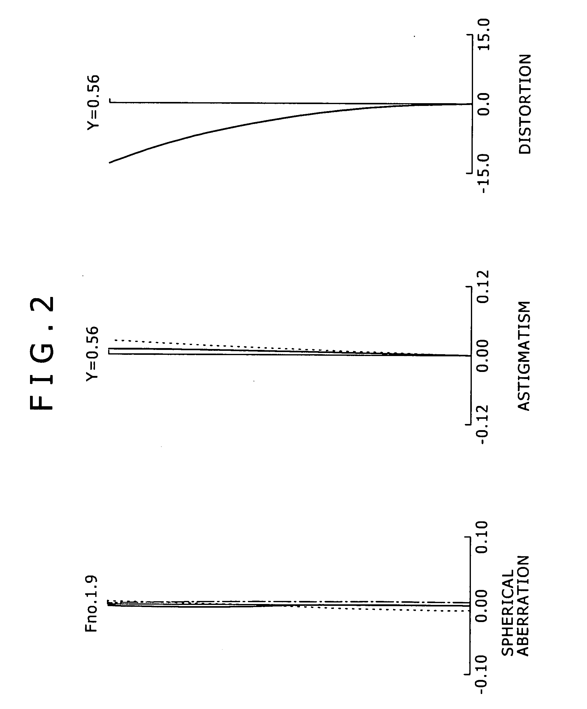
[0071] A change of a lens position state from the maximum wide-angle state to the maximum telephoto state results in changes of a surface gap D5 between the first lens group GR1 and the second lens group GR2, a surface gap D10 between the second lens group GR2 and the stop IR, a surface gap D13 between the third lens group GR3 and the fourth lens group GR4 and a surface gap D17 between the fourth lens group GR4 and the fifth lens group GR5. Such being the case, a table 2 shows values for each of the surface gaps D5, D10, D13 and D17 at the maximum wide-angle state (f=1.00), the mid-focal length (f=4.84) and the maximum telephoto state (f=23.45) according to the numerical embodiment 1 when the object distance is of infinity. A table 3 shows those when the object distance is of 2 m.
TABLE 2FOCAL LENGTH(AT INFINITY)14.84223.451D50.2775.3208.129D108.1563.1130.304D132.1980.9813.192D171.5912.8090.597
[0072]
TABLE 3FOCAL LENGTH(AT 2M)14.84223.451D50.2775.3208.129D108.1563.1130.304D132.1970.94...
second embodiment
[0077] The boom lens 1B includes eleven lenses in total, as shown in FIG. 9.
[0078] The first lens group GR1 has the positive refractive power on the whole, and is configured with three lenses L1, L2 and L3. It is noted that with respect to the lenses L1 and L2, a concave surface and a convex surface that are respectively on the image-plane side of the lens L1 and the object side of the lens L2 and have the same radius of curvature are cemented together into a cemented lens having a cemented surface R2.
[0079] The second lens group GR2 has the negative refractive power on the whole, and is configured with three lenses L4, L5 and L6. The second lens group GR2 is movable in position for movement in the direction of the optical axis for providing mainly zooming. It is noted that with respect to the lenses L5 and L6, a concave surface and a convex surface that are respectively on the image-plane side of the lens L5 and the object side of the lens L6 and have the same radius of curvature...
PUM
 Abstract
Description
Claims
Application Information
 - Generate Ideas
- Intellectual Property
- Life Sciences
- Materials
- Tech Scout
- Unparalleled Data Quality
- Higher Quality Content
- 60% Fewer Hallucinations
Browse by: Latest US Patents, China's latest patents, Technical Efficacy Thesaurus, Application Domain, Technology Topic, Popular Technical Reports.
© 2025 PatSnap. All rights reserved.Legal|Privacy policy|Modern Slavery Act Transparency Statement|Sitemap|About US| Contact US: help@patsnap.com