
Carriage assembly and storage medium drive

a technology of storage media and carriage assembly, which is applied in the direction of recording information storage, support for heads, instruments, etc., can solve the problems of troublesome connection between the first and second flexible printed wiring boards, and achieve the effect of fine alignment of the first terminal on the second terminal and convenient manner

Inactive Publication Date: 2007-12-06
FUJITSU LTD
View PDF6 Cites 21 Cited by
  • Summary
  • Abstract
  • Description
  • Claims
  • Application Information

AI Technical Summary

Benefits of technology

[0006]It is accordingly an object of the present invention to provide a carriage assembly and a storage medium drive, contributing to a fine alignment of a first terminal on a second terminal in a facilitated manner.
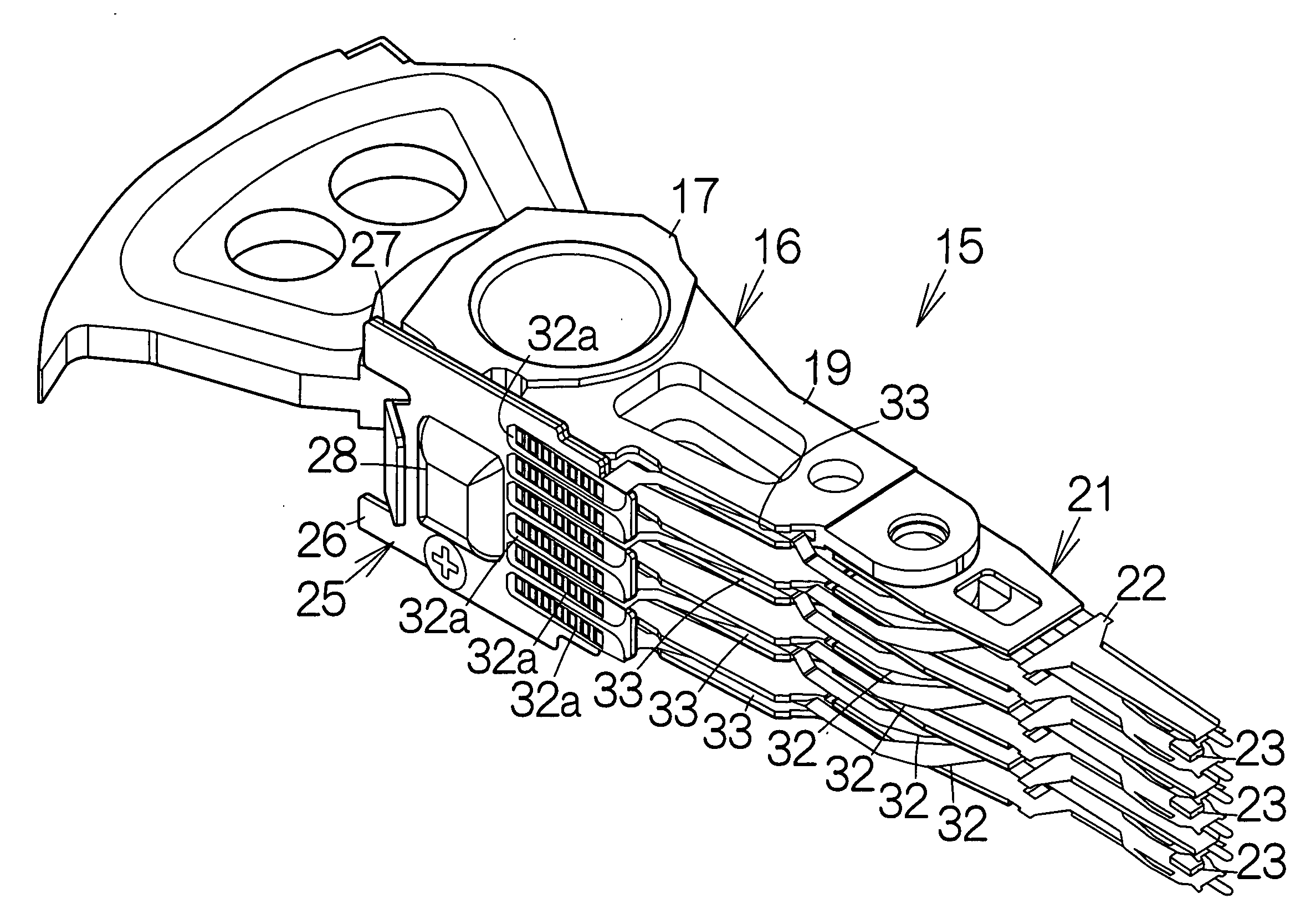
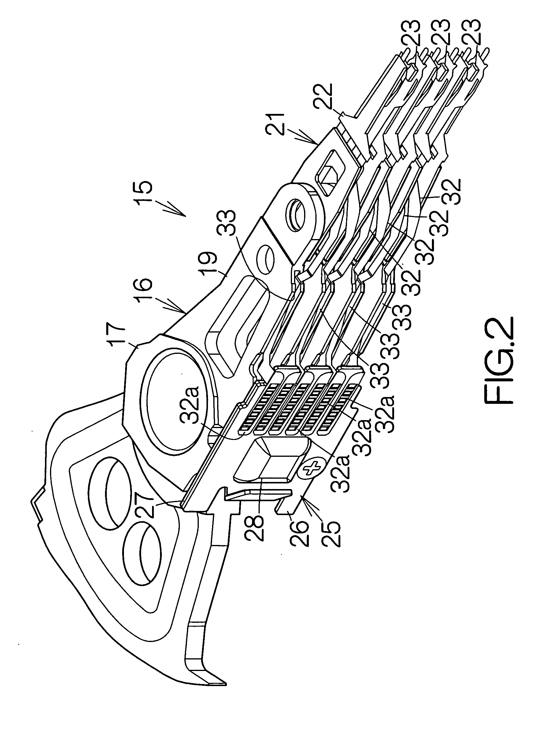
[0008]A step is formed on the first flexible printed wiring board in the carriage assembly. The step defines the wall surface facing the edge of the second flexible printed wiring board. A depression is thus defined on the first flexible printed wiring board, for example. The second flexible printed wiring board is overlaid on the first flexible printed wiring board when the first and second terminals are bonded to each other. In this case, when the second flexible printed wiring board is received in the depression, the second terminal can accurately be positioned on the first terminal in a facilitated manner. Furthermore, an operator is allowed to simply check with his eyes whether or not the second terminal is received in the depression, when he is required to check whether or not the second terminal is positioned right at the first terminal. The operator is not required to check the relative position between the first and second terminals with his eyes. This results in a significant reduction in the period of positioning the second terminal relative to the first terminal.
[0009]The step may be defined based on a film material attached to the surface of the first flexible printed wiring board. The film material contributes to an easier establishment of the step. The first flexible printed wiring board is not subjected to any change of design. Alternatively, the step may be defined based on a depression formed in the surface of the first flexible printed wiring board. The thickness of the first flexible printed wiring board may partially be changed so as to define the depression.
[0010]The height of the step may be set larger than the thickness of the second flexible printed wiring board in the carriage assembly. The second flexible printed wiring board can thus reliably be fitted in the depression inside the step. Once the second flexible printed wiring board is fitted in the depression, the second flexible printed wiring board can be held in the depression. The second flexible printed wiring board is kept in the depression when the second terminal is soldered to the first terminal. Working process can be simplified.
[0013]The carriage assembly allows the wall surface to face the first and second edges of the second flexible printed wiring board. The step may be formed to extend at a position adjacent to part of the second flexible printed wiring board. When the first and second edges of the second flexible printed wiring board collide against the wall surface, for example, the second terminal can accurately be positioned on the first terminal in a facilitated manner. Furthermore, an operator is allowed to simply check with his eyes whether or not the second terminal is arranged along the wall surface, when he is required to check whether or not the second terminal is positioned right at the first terminal. The operator is not required to check the relative position between the first and second terminals with his eyes. This results in a significant reduction in the period of positioning the second terminal relative to the first terminal.
[0018]The step is formed on the second flexible printed wiring board. The step defines a wall surface facing the edge of the first flexible printed wiring board. The first flexible printed wiring board is overlaid on the second flexible printed wiring board when the first and second terminals are bonded to each other. When the first flexible printed wiring board is positioned along the wall surface, the first terminal can accurately be aligned with the second terminal in a facilitated manner. This results in a significant reduction in the period of positioning the first terminal relative to the second terminal.

Problems solved by technology

It is troublesome to complete the connection between the first and second flexible printed wiring boards.

Method used


Image

  • Carriage assembly and storage medium drive
  • Carriage assembly and storage medium drive
  • Carriage assembly and storage medium drive

Examples


Embodiment Construction

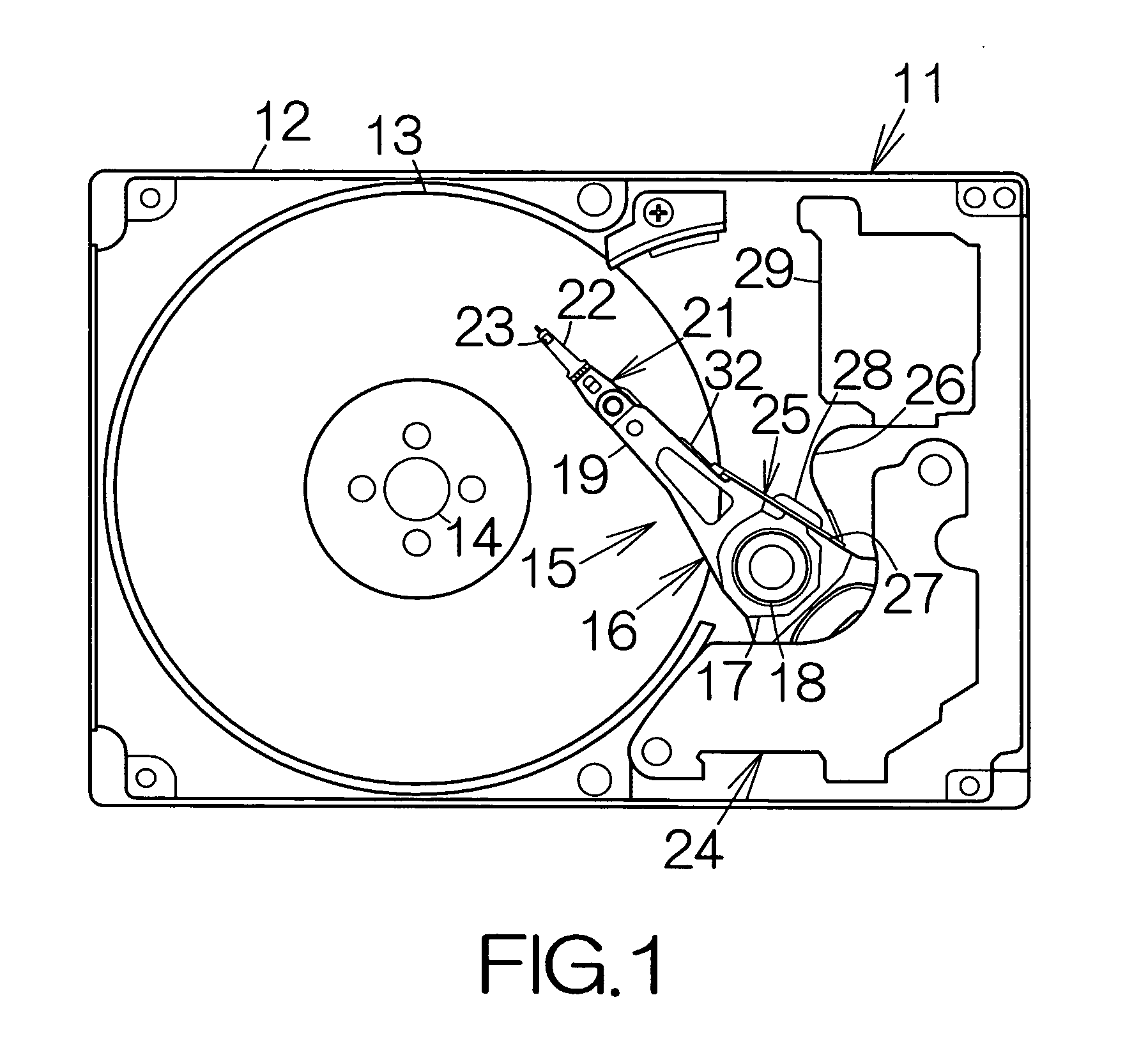
[0028]FIG. 1 schematically illustrates the inner structure of a hard disk drive, HDD, 11 as an example of a storage medium drive or storage device according to the present invention. The hard disk drive 11 includes a box-shaped enclosure base 12 defining an inner space of a flat parallelepiped, for example. The enclosure base 12 may be made of a metallic material such as aluminum, for example. Molding process may be employed to form the enclosure base 12. An enclosure cover, not shown, is coupled to the enclosure base 12. The enclosure cover closes the opening of the enclosure base 12. Pressing process may be employed to form the enclosure cover out of a plate material, for example.

[0029]At least one magnetic recording disk 13 as a storage medium is enclosed in the inner space of the enclosure base 12. The magnetic recording disk or disks 13 are mounted on the driving shaft of a spindle motor 14. The spindle motor 14 drives the magnetic recording disk or disks 13 at a higher revolut...


PUM


Abstract

A first flexible printed wiring board is attached to the supported end of a carriage. First terminals are exposed on the first flexible printed wiring board. A second flexible printed wiring board extending from a head slider toward the supported end of the carriage. The second flexible printed wiring board is overlaid on the first flexible printed wiring board. Second terminals are exposed on the second flexible printed wiring board. The second terminals are bonded to the first terminals. A step defines a wall surface facing the edge of the second flexible printed wiring board on the first flexible printed wiring board. A depression is defined on the first flexible printed wiring board. The second flexible printed wiring board is received in the depression, the second terminal can accurately be positioned on the first terminal in a facilitated manner.

Description

BACKGROUND OF THE INVENTION[0001]1. Field of the Invention[0002]The present invention relates to a storage medium drive including a first flexible printed wiring board attached to the supported end of a carriage and a second flexible printed wiring board extending from the tip end of the carriage toward the supported end of the carriage for connection to the first flexible printed wiring board.[0003]2. Description of the Prior Art[0004]A head suspension assembly having the structure of a so-called long-tail includes a first flexible printed wiring board extending backward from a head suspension as disclosed in Japanese Patent Application Publication No. 11-120715. When the head suspension assembly is attached to the tip end of a carriage arm, the tip end of the first flexible printed wiring board is connected to a second flexible printed wiring board attached to the side surface of a carriage. First terminals on the first flexible printed wiring board are positioned on the correspon...

Claims


Application Information

Patent Timeline
IPC IPC(8): G11B5/55
CPCG11B5/4846H05K3/281H05K3/363H05K2203/167H05K2201/058H05K2203/0191H05K2201/0394
Inventor KOBAYASHI, HIROAKITOKAIRIN, KOUICHISUZUKI, HIROFUMIYAMAGUCHI, HIDEKI
Owner FUJITSU LTD
Learn More