Variable Displacement Pump

a variable-displacement pump and pump chamber technology, applied in the direction of machines/engines, positive-displacement liquid engines, liquid fuel engines, etc., can solve the problem of rapid lightening of steering sensation, and achieve the effect of reducing the volume of the pump chamber

Inactive Publication Date: 2007-12-06
SHOWA CORP
View PDF4 Cites 16 Cited by
  • Summary
  • Abstract
  • Description
  • Claims
  • Application Information

AI Technical Summary

Benefits of technology

[0009]An object of the present invention is to maintain a discharge flow rate in a high rotating region constants in a variable displacement pump.
[0010]The present invention relates to a variable displacement pump comprising: a rotor fixed to a pump shaft inserted to a pump casing so as to be rotationally driven, and structured such that a plurality of vanes are accommodated in grooves so as to be movable in a radial direction; a cam ring fitted to a fitting hole within a pump casing so as to be movable and displaceable, forming a pump chamber with respect to an outer peripheral portion of the rotor, and forming first and second hydraulic chambers with respect to the pump casing; a discharge flow rate control apparatus introducing a pressure in an upstream side of a main throttle provided in a pump discharge side passage to the first hydraulic chamber, and introducing a pressure in a downstream side of the main throttle to the second hydraulic chamber; and the discharge flow rate control apparatus having a switch valve apparatus which is actuated on the basis of a pressure difference between the upstream and downstream sides of the main throttle, and controls a supply fluid pressure to the first hydraulic chamber in correspondence to a discharge flow rate of the pressurized fluid from the pump chamber. A suction port open to a suction region of the pump chamber is provided in an end surface of a side plate or a cover fixed to the pump casing so as to close a side portion of the cam ring. A first groove always connected to the second hydraulic chamber is provided in a slide surface of the cam ring facing to the end surface of the side plate or the cover. A second groove always connected to the suction port is provided in the end surface of the side plate or the cover. When the cam ring is moved to a moving end side in which a volumetric capacity of the pump chamber is reduced, the first groove and the second groove are connected, and the second hydraulic chamber is connectable to the suction port by the grooves.

Problems solved by technology

Therefore, an assist force in the high speed driving region becomes higher, and a steering feeling is rapidly light so as to become unstable.

Method used


Image

  • Variable Displacement Pump
  • Variable Displacement Pump
  • Variable Displacement Pump

Examples


Embodiment Construction

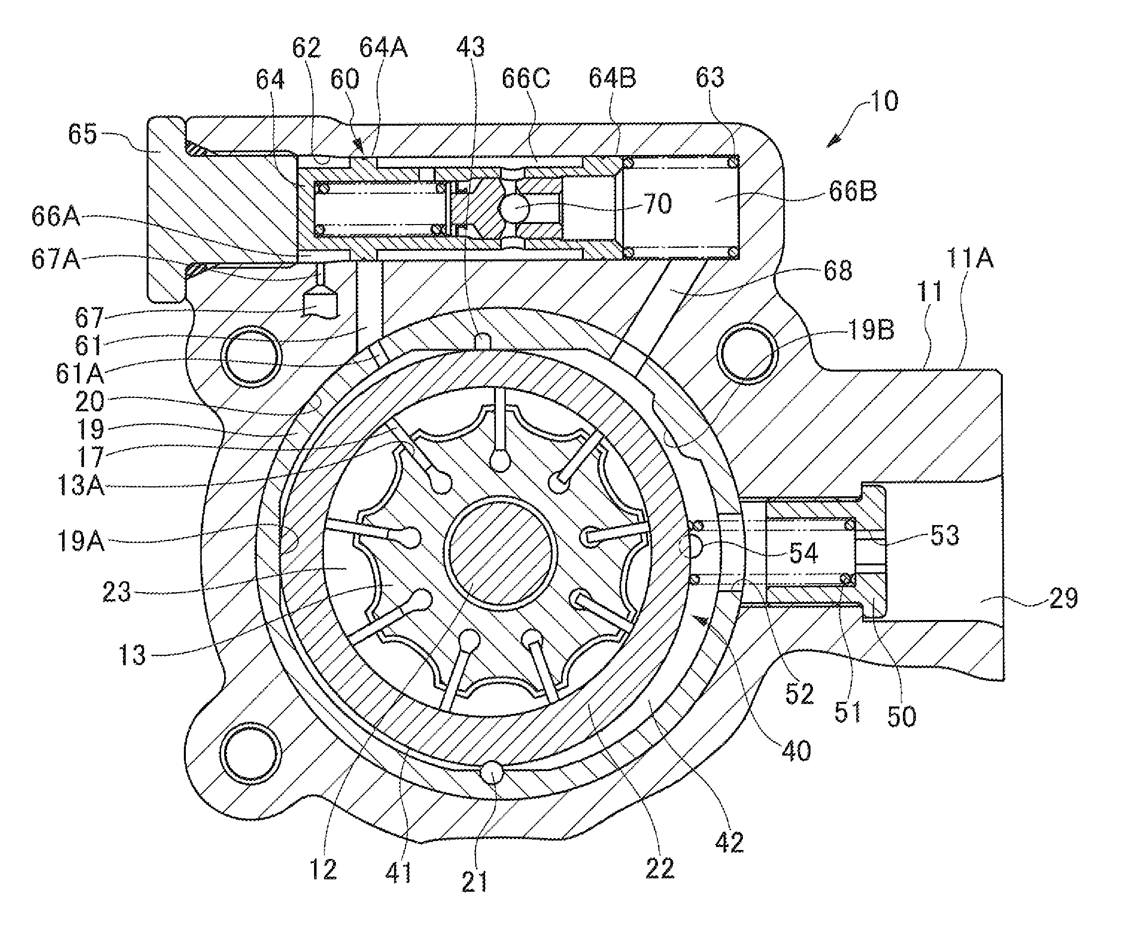
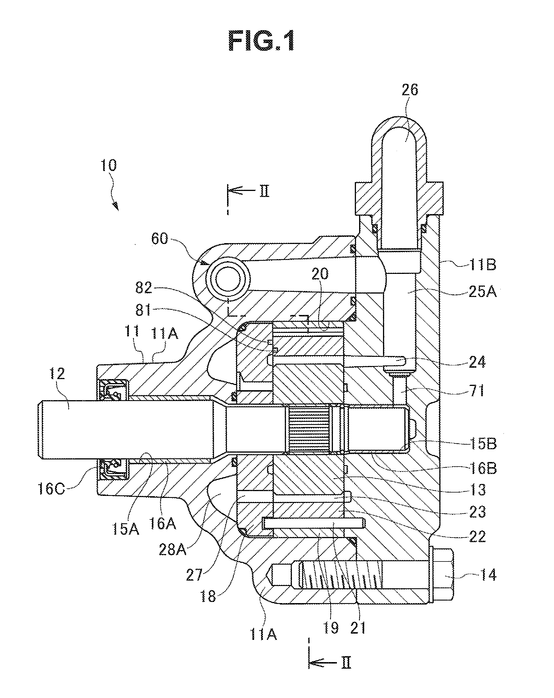
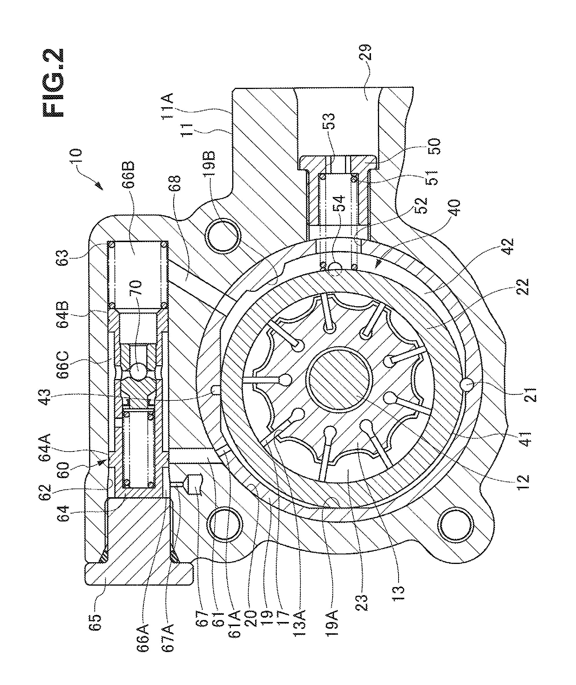
[0016]A variable displacement pump 10 corresponds to a vane pump forming a hydraulic pressure generating source of hydraulic equipment such as a power steering apparatus of a motor vehicle, and has a rotor 13 fixed to a pump shaft 12 inserted to a pump casing 11 by serration so as to be rotationally driven, as shown in FIGS. 1 and 2. The pump casing 11 is structured by integrating a pump housing 11A and a cover 11B by a bolt 14. The pump housing 11A is provided with a cup-shaped concave space accommodating a pump constituting element such as the rotor 13 or the like, and the cover 11B is combined with the pump housing 11A in such a manner as to close an opening portion of the concave space so as to be integrated. The pump shaft 12 is supported to a bearing 15A (a bush) provided in a support hole 15A of the pump housing 11A, and a bearing 16B (a bush) provided in a support hole 15B of the cover 11B. An oil seal 16C is fitted to the support hole 15A.

[0017]The rotor 13 accommodates van...


PUM


Abstract

In a variable displacement pump, a first groove always connected to a second hydraulic chamber is provided in a slide surface of a cam ring facing to an end surface of a side plate, and a second a groove always connected to a suction port is provided in the end surface of the side plate, whereby when the cam ring is moved to a moving end side in which a volumetric capacity of a pump chamber is reduced, the first groove and the second groove are connected, and the second hydraulic chamber can be connected to the suction port by the grooves.

Description

BACKGROUND OF THE INVENTION[0001]1. Field of the Invention[0002]The present invention relates to a variable displacement pump. The pump may be used, for example, in a hydraulic power steering apparatus for a motor vehicle or the like.[0003]2. Description of the Related Art[0004]A variable displacement pump used in a hydraulic power steering apparatus for a motor vehicle is driven by an engine of the motor vehicle, and a discharge flow rate is increased in accordance that a rotating speed of the engine or a rotating speed of the pump becomes higher. On the contrary, in the hydraulic power steering apparatus for the motor vehicle, a high assist force is necessary during stopping or a low speed traveling region, and lower assist force is desirable in a high speed traveling region, to improve a steering property and driving stability.[0005]A variable displacement pump is described in Japanese Patent No. 3501990 (patent document 1). A rotor is fixed to a pump shaft inserted to a pump cas...

Claims


Application Information

Patent Timeline
Patent Type & Authority Applications(United States)
IPC IPC(8): F01C20/18
CPCF04C14/226F04C2/344
Inventor UEKI, TAKESHIISHIGE, SHINGOYAMADA, YOSHINOBU
Owner SHOWA CORP
Why Eureka
Try Eureka