Reaction device and method
A reaction device and reaction technology, which are applied in the preparation of test samples, electrochemical variables of materials, etc., can solve the problems of difficulty in controlling the importance of the installation position of PT100, difficult cleaning of the reaction cup, neglect of reading temperature, etc., so as to improve the temperature measurement. Accuracy, small waste volume, and the effect of reducing volume capacity
- Summary
- Abstract
- Description
- Claims
- Application Information
AI Technical Summary
Problems solved by technology
Method used
Image
Examples
Embodiment 1
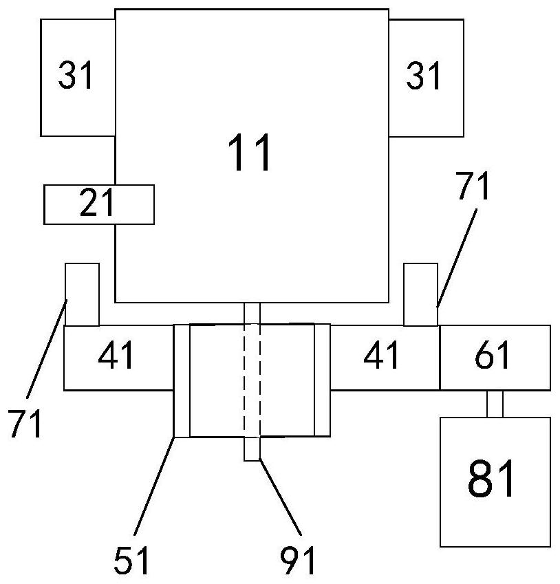
[0027] figure 1 The structural diagram of the reaction device of the embodiment of the present invention is schematically provided, as figure 1 Shown, described reaction unit comprises:
[0028] A reaction chamber 11, a heating module 31 and a temperature measuring module 21, wherein the reaction chamber 11 has a stirrer;
[0029] A pipeline 91, the pipeline 91 is arranged on the lower side of the reaction chamber 11 and communicates with the opening at the bottom of the reaction chamber 11;
[0030] A rotating disk 41 and a bracket 51, the rotating disk 41 is arranged on the bracket 51 and is located on the lower side of the reaction chamber 11, and the pipeline 91 passes through the rotating disk 41;
[0031] A magnet 71, the magnet 61 is arranged on the rotating disk 41;
[0032] The driving module 81 indirectly drives the rotating disk 41 to rotate.
[0033] In order to drive the rotating disk indirectly, further, the reaction device also includes:
[0034] The transm...
Embodiment 2
[0063] An application example of the reaction device and method according to Example 1 of the present invention in water quality analysis.
[0064] In this application example, if figure 1 As shown, the center of the bottom end of the reaction chamber 11 has a through hole, and the pipeline 91 communicates with the through hole. The pipeline 91 is used to inject liquid and air (for stirring) into the reaction chamber 11 respectively, and to discharge waste liquid. The pipeline 91 passes through the said through hole. The rotating disk 41 and the bracket 51; the rotating disk 41 adopts a gear, is arranged on the bracket 51, and is located on the underside of the reaction chamber 11, and the pipeline 91 passes through the rotating disk 41; the magnet 71 is arranged on the rotating disk 41, the connection line between the two magnets 71 passes through the rotating shaft of the rotating disk 41; the driving module 81 adopts a motor, and the transmission member 61 adopts a gear, wh...
PUM
 Abstract
Description
Claims
Application Information
 - R&D
- Intellectual Property
- Life Sciences
- Materials
- Tech Scout
- Unparalleled Data Quality
- Higher Quality Content
- 60% Fewer Hallucinations
Browse by: Latest US Patents, China's latest patents, Technical Efficacy Thesaurus, Application Domain, Technology Topic, Popular Technical Reports.
© 2025 PatSnap. All rights reserved.Legal|Privacy policy|Modern Slavery Act Transparency Statement|Sitemap|About US| Contact US: help@patsnap.com


