
Apparatus For Generating Electric Current Field In The Human Body And Method For The Use Thereof

a technology of electric current field and human body, applied in the direction of magnetotherapy, magnetotherapy using variable magnetic fields, therapy, etc., can solve the problems of complex non-linear problems, non-invasive use of electrodes on the skin, and ineffective neurostimulation,

Inactive Publication Date: 2007-12-06
UMC UTRECHT HLDG BV
View PDF11 Cites 90 Cited by
  • Summary
  • Abstract
  • Description
  • Claims
  • Application Information

AI Technical Summary

Benefits of technology

The present invention relates to a method and apparatus for non-invasive spatially selective neurostimulation. The invention is based on the idea of using rotating magnets in a way that maximizes the accumulation of charge inside the tissue while reducing the accumulation in other areas. This is achieved by rotating the magnets in a way that maximizes the Lorentz force while minimizing the accumulation of eddy currents. The invention also includes additional features such as the use of multiple rotating magnetic elements and the use of electromagnets or magnetizable objects. The technical effect of the invention is the creation of a maximum in the stimulation field that can be located deep inside the tissue.

Problems solved by technology

This fundamental limitation is also valid if multiple magnets and electrodes are used.
Calculation of the J(x) distribution on basis of the given Eapplied(x) en σ(x) distributions is, generally speaking, a complicated non-linear problem.
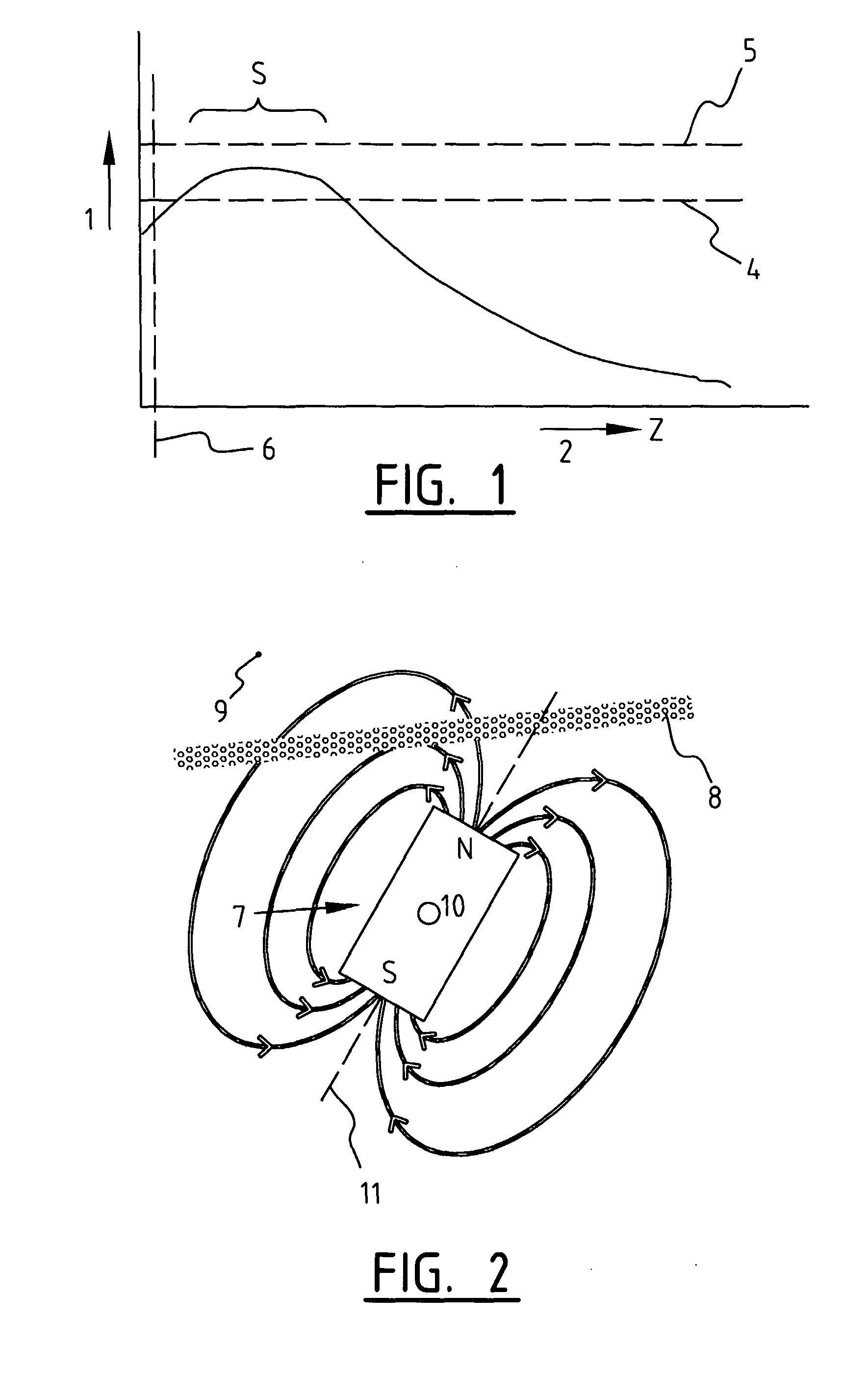
The use of electrodes on the skin is a simple, but not very effective way to achieve neurostimulation in tissues that are located deep inside the body, because the electrostimulation in the tissue caused by the electrodes is such that the point of maximum current density is located in the immediate vicinity of the electrodes, i.e.: near the skin, whereas in the other tissues, in case of a completely homogeneous conductivity distribution, the current distribution is spread out without any maxima or minima deeper inside the tissue.
Since however the invasive nature of the invasive electrodes has many serious disadvantages, the need for non-invasive, spatially selective stimulation of deeper tissues is still remaining.

Method used


Image

  • Apparatus For Generating Electric Current Field In The Human Body And Method For The Use Thereof
  • Apparatus For Generating Electric Current Field In The Human Body And Method For The Use Thereof
  • Apparatus For Generating Electric Current Field In The Human Body And Method For The Use Thereof

Examples


Embodiment Construction

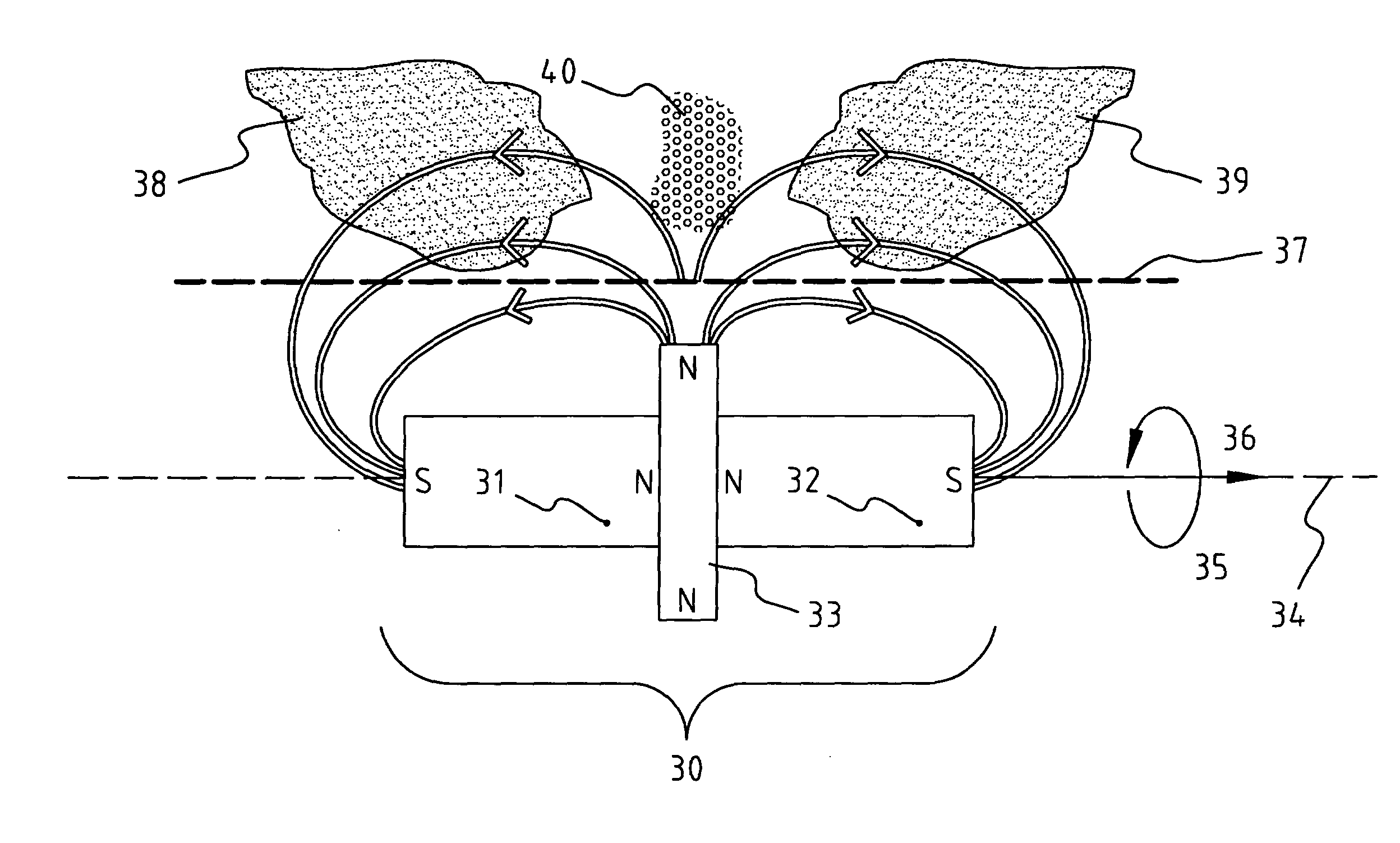
[0111] A number of preferred embodiments of the present invention are possible, in which the number of magnets and the configurations of magnets vary, as well as the ways in which the fast rotation of the magnets is achieved. In the following, indicated by the label ‘(a)’, a simple preferred embodiment is described; and, subsequently, indicated by labels ‘(b)’ and ‘(c)’, more advanced methods to obtain fast rotation of the magnetic elements are described.

[0112] (a) A simple embodiment uses at least two rotating magnetic elements (see FIG. 9), and uses preferably three magnetic elements. As an example, an apparatus is described here using two magnetic elements, indicated by M1 and M2, respectively. Both magnetic elements are equal in shapes and design; the essential differences between M1 and M2 are that M1 is much larger than M2, and that M1 rotates faster than M2, and that M2 is located directly near the skin, whereas M1 is located at a larger distance to the skin. Furthermore, ei...


PUM


Abstract

The present invention relates to an apparatus for generating an electrical current field in the human body, comprising two or more rotatable magnetic elements for generating of a composite magnetic field, which magnetic elements are positioned such that each magnetic element is rotatable around an axis of rotation; means for producing a rotating motion of the magnetic elements such that upon rotation of one or more of the magnetic elements the composite magnetic field remains substantially constant; and means for disturbing the composite magnetic field, for altering the magnetic field entirely.

Description

[0001] Non-invasive electromagnetic neurostimulation has many applications, such as the treatment of neuro-physiological diseases, investigation of function, and pain treatment. For the application of neurostimulation for the sake of pain treatment, the Gate-Control theory (of Melzack and Wall) is important. According to this theory, the transportation of signals along pain-sensitive nerves (C-fibers) can be mitigated by simultaneous stimulation of another type of nerves, viz. the ‘thick fibers’ (T-fibers), which are not pain-related. In this way, pain treatment can be performed using localized and specific stimulation of thick fibers only. This theory is the basis for known pain treatment techniques, such as TENS (Transcutaneous Electrical Nerve Stimulation) and ESES (Epidural Spinal Electrical Stimulation). [0002] The basic principle of electromagnetic neurostimulation is to produce an electric field in neuronal tissue in such a way, that it causes the excitation of neurons. [0003...

Claims


Application Information

Patent Timeline
Patent Type & Authority Applications(United States)
IPC IPC(8): A61N2/04A61N2/00A61N2/12
CPCA61N2/006
Inventor KONINGS, MAURITS
Owner UMC UTRECHT HLDG BV
Learn More