Driving assist system for vehicle
- Summary
- Abstract
- Description
- Claims
- Application Information
AI Technical Summary
Benefits of technology
Problems solved by technology
Method used
Image

Examples
first embodiment
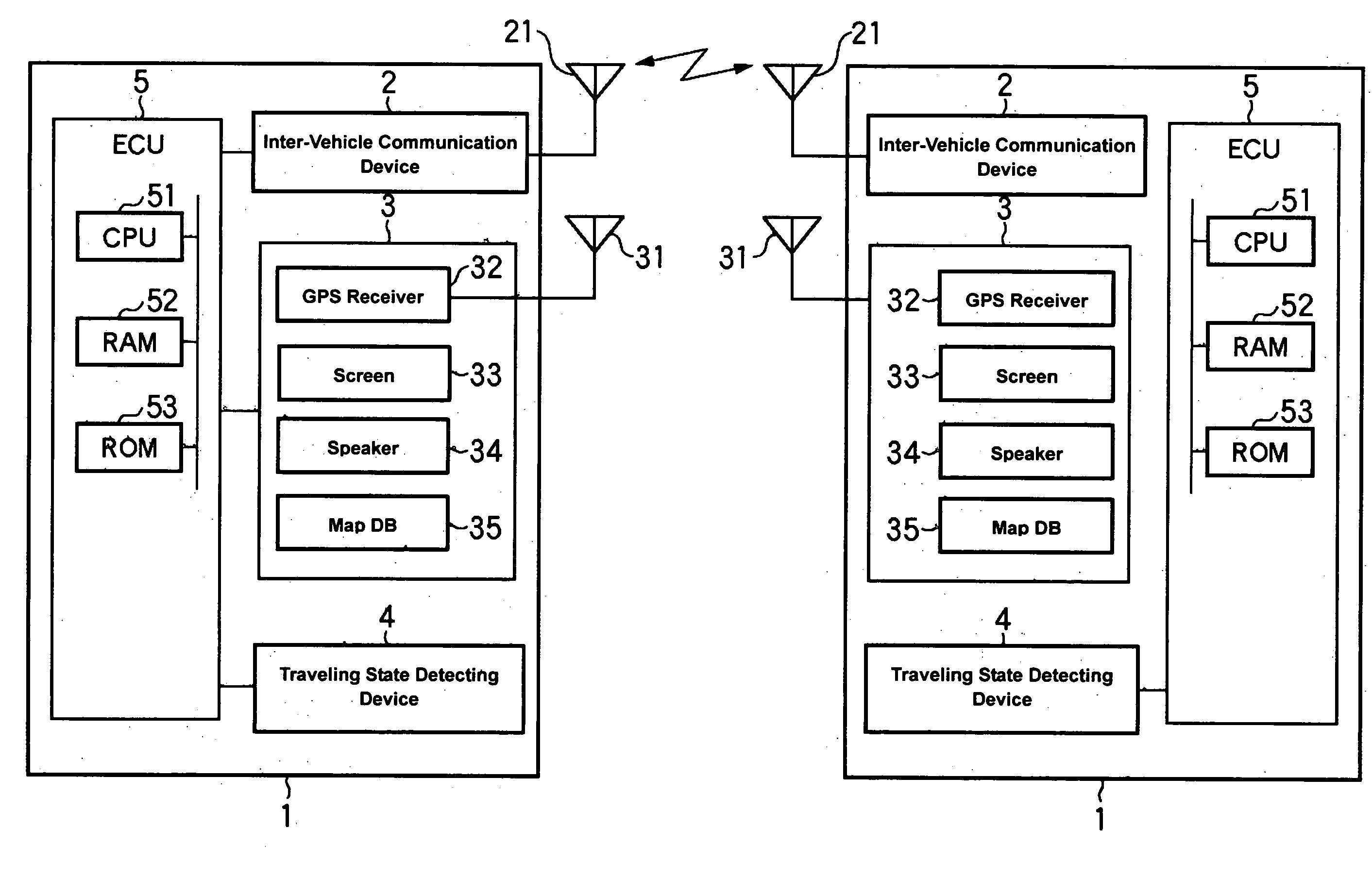
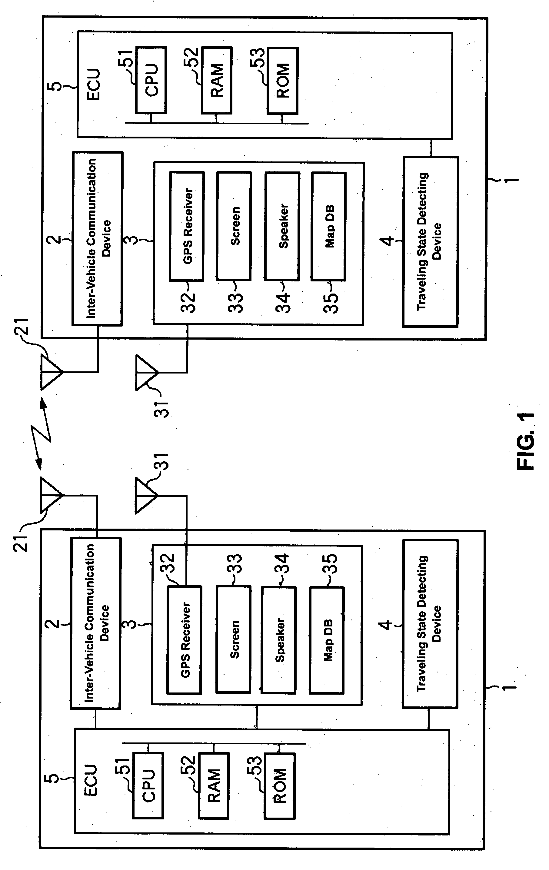
[0050]FIG. 1 is a block diagram showing a structure of a driving assist system according to the present invention.
[0051]A driving assist system 1 that is installed on a vehicle in FIG. 1 comprises an inter-vehicle communication device 2 that transmits and receives various information between the own vehicle and another vehicle (one or more vehicles; hereinafter referred to as “another vehicle” regardless of the number of vehicles just for simplicity) equipped with the same system (which may be also refereed to as a partner vehicle(s) or a vehicle(s) traveling on an opposite traffic lane), a car navigation device 3, a traveling state detecting device 4 that outputs information regarding a traveling state of the own vehicle, and an ECU 5 to conduct a driving assist control in which a possible collision between the own vehicle and another vehicle that exists around the own vehicle is predicted based on the various information obtained from the above-described devices 2, 3 and 4, and in...
embodiment 1
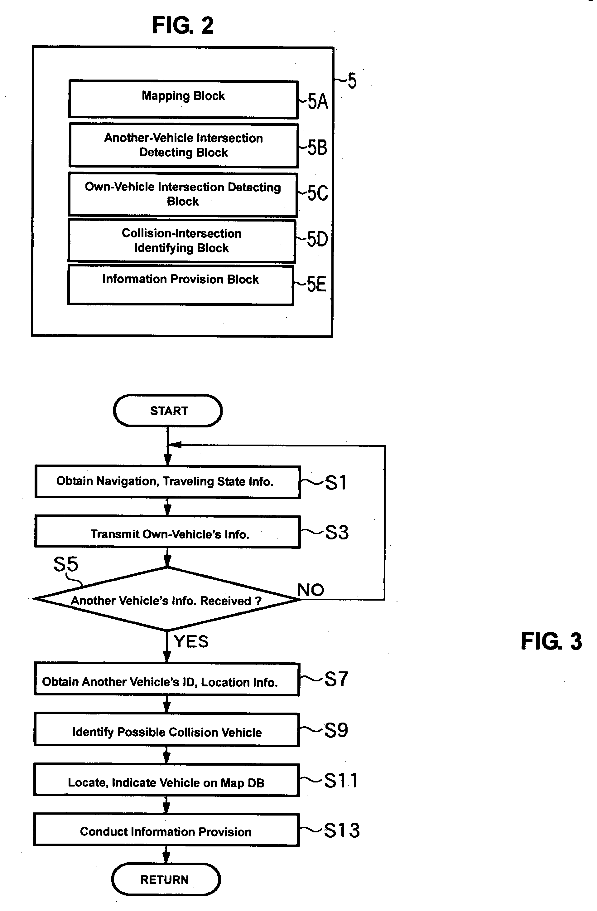
[0072][Indication of Vehicle Having Collision Possibility: Embodiment 1]
[0073]FIG. 4 is a flowchart showing an identification process of a vehicle having the collision possibility in step S9 of FIG. 3. FIG. 5 is an explanatory diagram showing the identification process of the vehicle having the collision possibility of FIG. 4.
[0074]In FIGS. 4 and 5, the ECU 5, as the own-vehicle intersection detecting block 5C, obtains the information of the intersection in front of the own vehicle (hereinafter, referred to as “forward-intersection information”) and the traveling road information of the own vehicle from the map DB based on the own vehicle's location (S21). Herein, it obtains a location of an own vehicle A, intersections iii, vii, vi, and traveling road II that are shown in FIG. 5.
[0075]Then, the ECU 5 detects an intersection that is located right before the own vehicle (hereinafter, referred to as “right-before intersection”) among the intersections in front of the own vehicle, and ...
embodiment 3
[0083]Next, the ECU 5 identifies an object of another vehicle having the collision possibility based on the approaching directions to the intersection (S31). Herein, the vehicle B1 (approaching from the west), B4 (approaching from the east) may be identified as the object of another vehicle having the collision possibility in case of predicting the above-described sudden-meeting collision. The vehicle B5 (approaching from the north) may be identified as the object of another vehicle having the collision possibility in case of predicting the right-turn collision. And, the vehicle B8 (approaching from the south) may be identified as the object of another vehicle having the collision possibility in case of predicting the left-turn collision. Namely, the object of another vehicle, to which the predicted collision, information provision, and the like need to be provided, can be properly selected by identifying the approaching direction to the intersection, like an embodiment 3 that will ...
PUM
 Abstract
Description
Claims
Application Information
 - R&D
- Intellectual Property
- Life Sciences
- Materials
- Tech Scout
- Unparalleled Data Quality
- Higher Quality Content
- 60% Fewer Hallucinations
Browse by: Latest US Patents, China's latest patents, Technical Efficacy Thesaurus, Application Domain, Technology Topic, Popular Technical Reports.
© 2025 PatSnap. All rights reserved.Legal|Privacy policy|Modern Slavery Act Transparency Statement|Sitemap|About US| Contact US: help@patsnap.com