
Break-away multi-purpose flooring transition

a multi-purpose, transition technology, applied in the direction of roof tools, structural elements, metal sawing apparatus, etc., can solve the problems of difficulty in covering the gap that may be formed, problems encountered with conventional edge molding, etc., to enhance or supplement the fit and positioning

Inactive Publication Date: 2007-12-13
PFLEIDERER SCHWEIZ
View PDF24 Cites 42 Cited by
  • Summary
  • Abstract
  • Description
  • Claims
  • Application Information

AI Technical Summary

Benefits of technology

[0011] The outward-facing surface of the assembly may be formed as a single, unitary, monolithic surface that covers both the first and second arms. This outward-facing surface may be decorated, for example, with a laminate or a paper, such as a monochromatic or patterned décor, impregnated with a resin, in order to increase its aesthetic value, to match, blend or contrast with the floor panels. Preferably, the outward facing surface has incorporated therein at least one material to increase its abrasion resistance, such as at least one type of hard particles of silica, alumina, diamond, silicon nitride, aluminum oxide, silicon carbide, cerium oxide and similar hard particles, preferably having a Moh's hardness of at least approximately 6. This outward-facing surface may also be covered with other types of coverings, such as cork, foils (such as paper or thermoplastic foils), paints, papers (optionally stainable), polyurethane (optionally cured), printable surfaces (which may be the surface itself), fiber glass, glass fiber reinforced plastics, or a variety of other decorative elements, including, but not limited to, wood veneer, ceramic (such as tiles), metal, vinyl or other decorative materials.
[0016] An adhesive, such as a glue, a microballoon adhesive, contact adhesive, or chemically activated adhesive, including a water-activated adhesive, may be also positioned on any of the pieces of the assembly to either hold the assembly together or in place. Of course, such an adhesive is not necessary, but may enhance or supplement the fit and positioning of the assembly over the gap between the floor elements. Additionally, the adhesive may assist in creating a more air-tight or moisture-tight joint.

Problems solved by technology

A problem is encountered, however, when flooring materials that are dissimilar in shape or texture are used.
For example, when a hard floor is placed adjacent a carpet, problems are encountered with conventional edge moldings placed therebetween.
Such problems include difficulty in covering the gap that may be formed between the floorings having different height, thickness or texture.

Method used


Image

  • Break-away multi-purpose flooring transition
  • Break-away multi-purpose flooring transition
  • Break-away multi-purpose flooring transition

Examples


Embodiment Construction

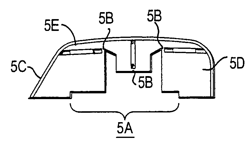
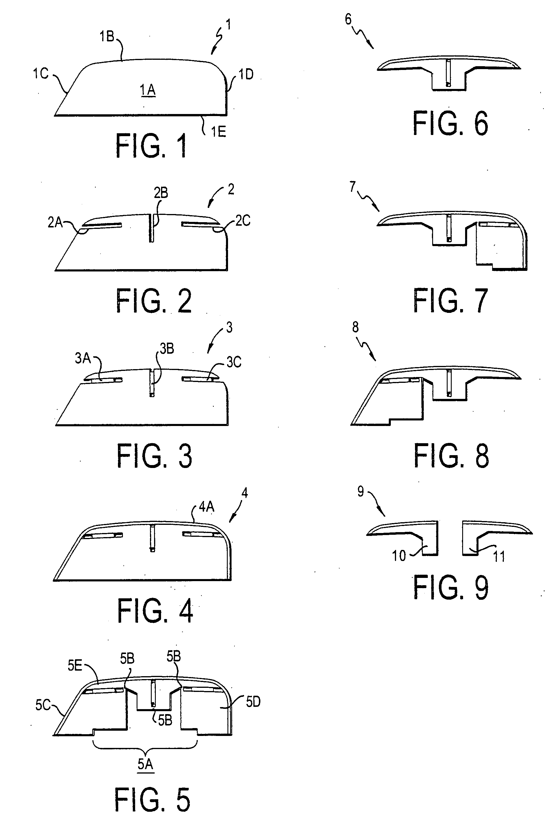
[0061]FIG. 1 shows a structure 1, from which the present invention can be formed. Structure 1 typically has a core 1A, an upper face 1B, a first lateral face 1C, a second lateral face 1D and a lower face 1E.

[0062] Preferably, core 1A is formed from a fiberboard, such as high-density fiberboard (HDF) or medium-density fiberboard (MDF), plastic, wood, engineered wood, metal, composites, gypsum, high-density fiber reinforced plaster, or other natural or synthetic material such as cork, or any additional material, such as described in U.S. Pat. No. 6,860,074, herein incorporated by reference in its entirety. Preferred plastics include extrudable thermoset and thermoplastic resins, the latter including high density olefins and polyvinylchloride. In preferred embodiments of the invention, the core 1A is unitary, i.e., it is a single piece / unit, not a multi-piece element, held together by glues, adhesives, joints, etc.

[0063] The decorative outer face can have a variety of finishes, such ...


PUM

PropertyMeasurementUnit
Densityaaaaaaaaaa
Hardnessaaaaaaaaaa

Abstract

The invention is a joint cover assembly for covering a gap adjacent an edge of a panel that covers a sub-surface, and a method of covering such a gap. The assembly can be manipulated to form an end molding, a T-molding, a hard surface reducer, a carpet reducer, and / or a stair nose molding. A kit can include the joint cover assembly an a tool for forming a flooring transition from a generic element having break-away sections.

Description

CROSS-REFERENCE TO RELATED APPLICATIONS [0001] This application claims priority from U.S. Provisional Appl. No. 60 / 808,121, having been filed May 25, 2006, incorporated by reference in its entirety.BACKGROUND [0002] 1. Field of the Invention [0003] The invention is an integral multi-purpose structure which can be separated into various flooring transitions such as T-moldings, hard surface reducers and end moldings. [0004] 2. Background of the Invention [0005] Hard surface floors, such as wood or laminate flooring, have become increasingly popular. As such, many different types of this flooring have been developed. Generally, this type of flooring is assembled by providing a plurality of similar panels. The differing types of panels that have developed, of course, may have differing widths and thicknesses. The same is true when a laminate floor (often referred to as a “floating floor”) abuts another hard surface, such as a resilient surface (such as vinyl), tile or another laminate s...

Claims


Application Information

Patent Timeline
IPC IPC(8): E04F19/02
CPCB23D45/003B23D45/102B26D3/001E04F19/02Y10T29/49E04F19/062E04F19/065E04F19/066E04F11/166E04F19/061
Inventor STANCHFIELD, OLIVERKORNFALT, SVENLARSSON, ROLANDPIERCE, WILLIAM T.LA SERNA, SABADSMITH, PATRICK GEORGEJOHNSTON, WAYNE ROBERT
Owner PFLEIDERER SCHWEIZ
Learn More