System And Method For Rigging Up Well Workover Equipment

a technology for workover equipment and recovery systems, which is applied in the field of gas and oil recovery systems for rigging up well workover equipment, can solve the problems of heavy equipment and achieve the effect of facilitating the rigging up of elements

Inactive Publication Date: 2007-12-13
VETCO GRAY SCANDINAVIA
View PDF26 Cites 51 Cited by
  • Summary
  • Abstract
  • Description
  • Claims
  • Application Information

AI Technical Summary

Benefits of technology

[0006] It is an object of the present invention to present a gas and oil recovery system that makes the rigging of parts of such a system upon heaving vessel movement at sea simpler and safer than do contemporary systems. Especially, the invention should facilitate the rigging up of elements on top of the surface flow head.

Problems solved by technology

Movement of the open water workover riser surface flowhead due to vessel movement complicates rig-up of well workover equipment on top.
This is particularly an issue with rig up of coiled tubing (CT), where the equipment is heavy.
Rig up / rig down involves deploying / retracting a coiled tubing / toolstring, which might be difficult upon heaving motion of the vessel.

Method used


Image

  • System And Method For Rigging Up Well Workover Equipment
  • System And Method For Rigging Up Well Workover Equipment
  • System And Method For Rigging Up Well Workover Equipment

Examples


Embodiment Construction

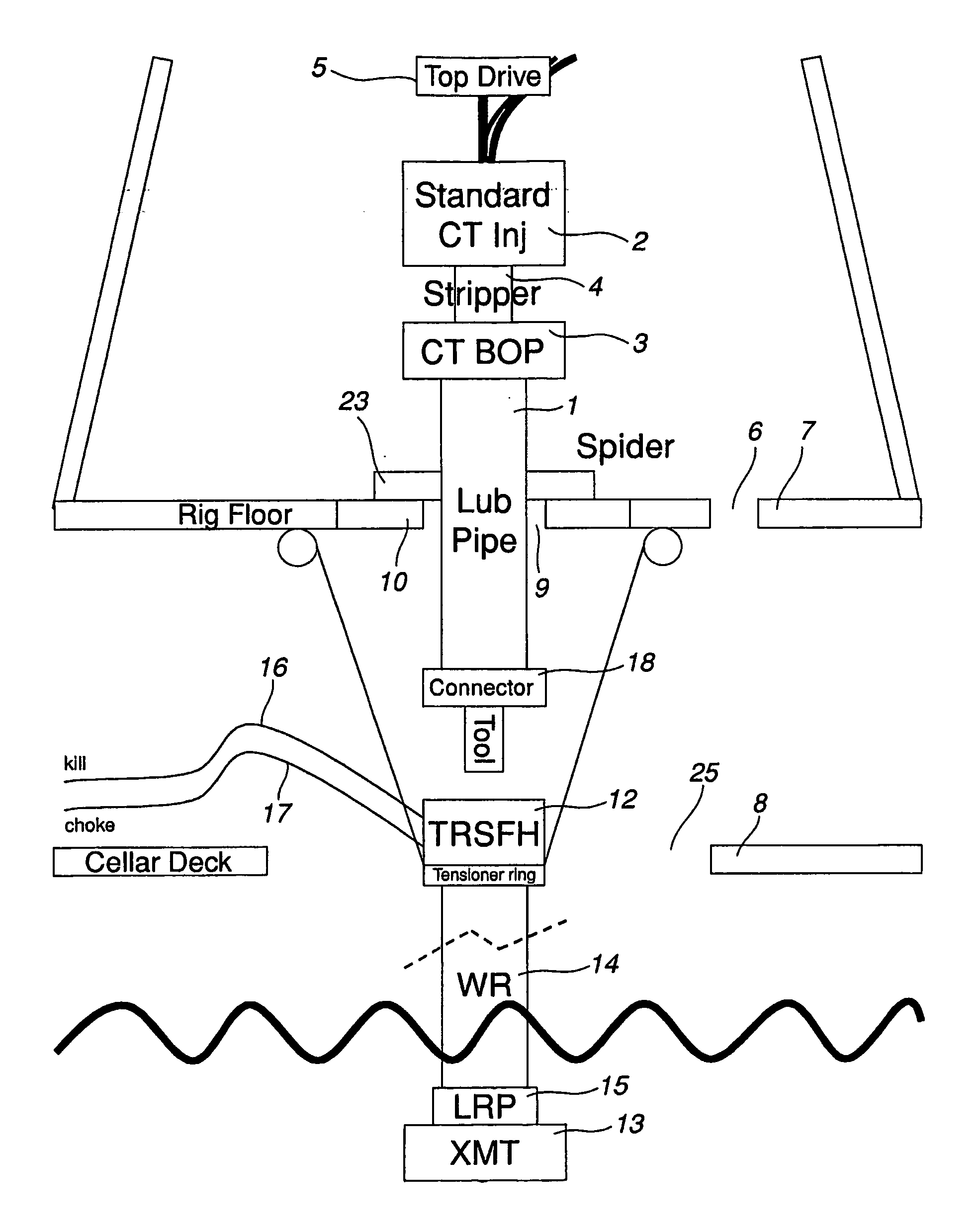
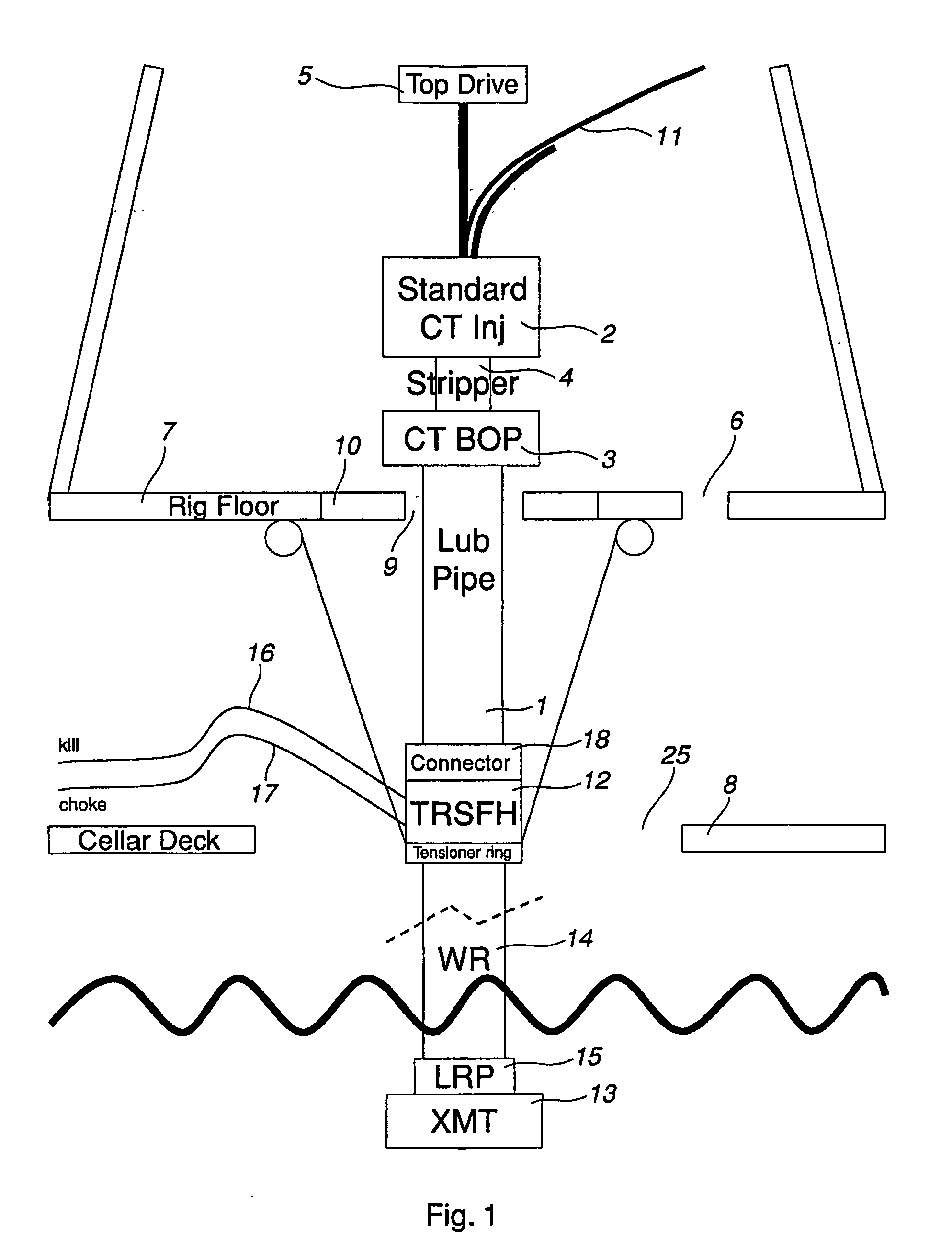
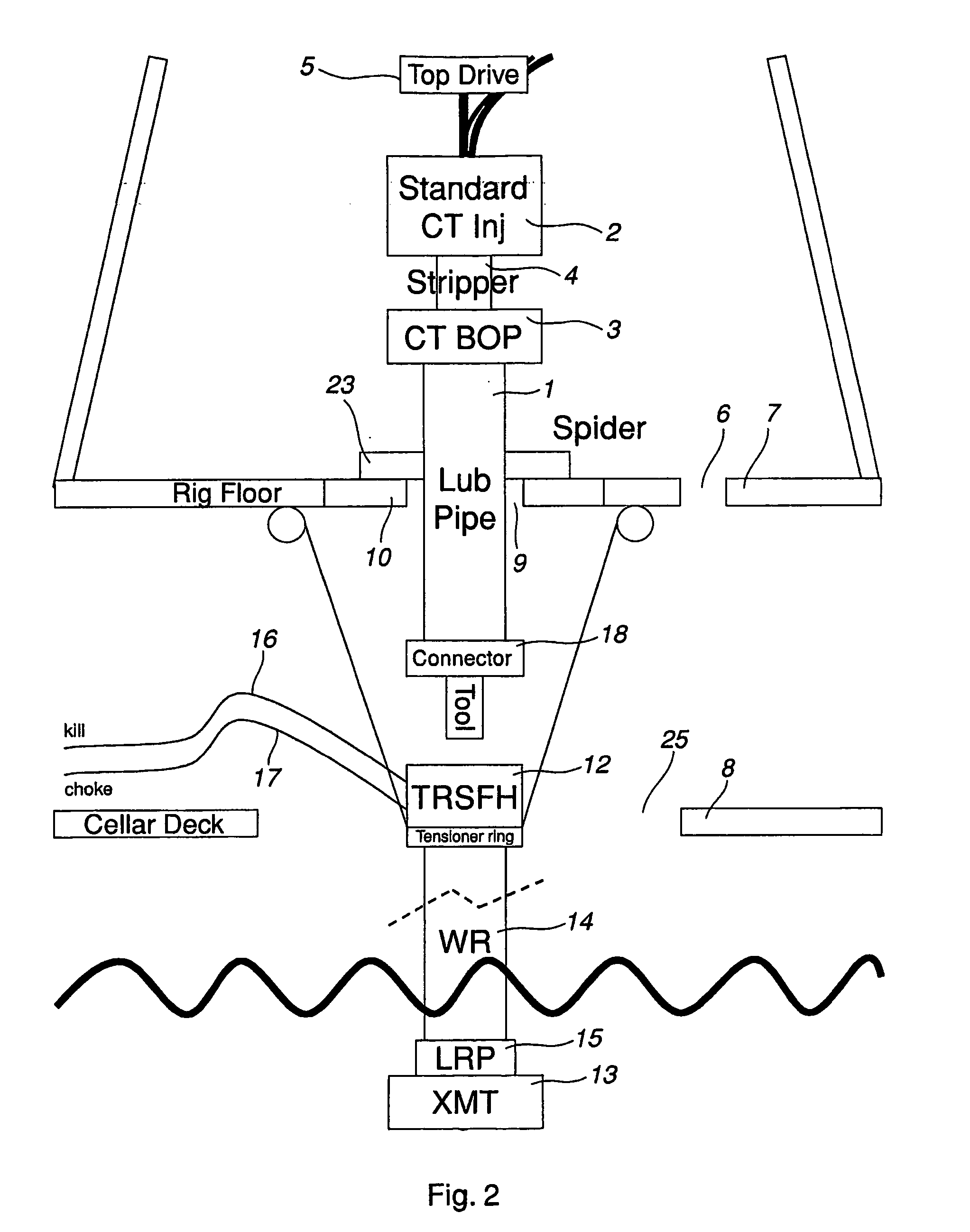
[0036] In order to facilitate the understanding of the following detailed description, some elements that are commonly used in a gas or oil recovery system will be explained more in detail as to their main functions and main components. Not all of these elements are essential for the present invention, but should be mentioned anyhow for the sake of clarity.

[0037] Surface Flow Head, SFH (also named Surface Flow Tree, SFT): acts as a coupling or crossover between the Workover Riser and the wireline or Coiled Tubing equipment (the Coiled Tubing WBP or Lubricator Pipe) arranged on top of the SFH, with inlets for the Kill and choke lines respectively. The SFH mainly comprises a pressure containing body with one valve in the main bore and two side outlets with valves. The Kill and choke lines are attached to each of these outlets. The lower end of the SFH is equipped with a swivel, which allows it to be rotated independently with relation to the Workover Riser (around an axis running thr...


PUM


Abstract

A gas and oil recovery system including a vessel, platform or rig, with a rig floor, a riser including a pipe that extends from the vessel, platform or rig to a x-mas tree on top of a well head and via which a wire or coiled tubing is fed down into a well. The riser is movable through an opening in the rig floor, and a surface flow head connected to the riser and to a wire line or coiled tubing equipment. The surface flow head is arranged to be run through the opening in the rig floor.

Description

FIELD OF THE INVENTION [0001] The present invention relates to a gas and oil recovery system for rigging up well workover equipment, comprising a platform, vessel or rig, with a rig floor, a riser, comprising a pipe that extends from the vessel, platform or rig to a subsea x-mas tree on top of a well head and via which a wire or coiled tubing is fed down into a well, said riser being movable through an opening in said rig floor, and a surface flow head connected to the riser on one hand and to a wire line or coiled tubing equipment on the other hand. In particular, the platform, rig or vessel is a floating construction. [0002] The present invention also relates to a method of rigging up a gas and oil recovery system comprising well workover equipment according the invention. [0003] In particular, the present invention relates to a system and method that can address problems associated with establishing and maintaining connections between individual workover equipment components duri...

Claims


Application Information

Patent Timeline
Patent Type & Authority Applications(United States)
IPC IPC(8): E21B23/00E21B17/01E21B31/00E21B19/00E21B19/22E21B33/038E21B33/064E21B33/068
CPCE21B19/004E21B19/22E21B33/068E21B33/064E21B33/038
Inventor HAHEIM, SVEIN A.
Owner VETCO GRAY SCANDINAVIA
Why Eureka
Try Eureka