Surface Textures for Earth Boring Bits

a surface texture and earth boring technology, applied in the field of earth boring bits, can solve the problems of large static load, large transient or shock load, etc., and achieve the effects of preventing side leakage of lubricant, maximizing lubrication performance, and improving shock absorption

Active Publication Date: 2007-12-13
BAKER HUGHES INC
View PDF5 Cites 26 Cited by
  • Summary
  • Abstract
  • Description
  • Claims
  • Application Information

AI Technical Summary

Benefits of technology

[0009]The orientation and the size and shape of the surface texture have a significant influence on its effectiveness on bearing performance. In one preferred embodiment, the grooves of the surface texture run parallel to the direction of the flow of the lubricant. This will help prevent side leakage of the lubricant. In another preferred embodiment the grooves of the surface texture run perpendicular to the direction of the flow of the lubricant, which will generate extra hydrodynamic force. When considering the rotating components, the preferred embodiment would be to apply the surface texture to the rotating surface. Alternatively, when applying the surface texture to improve shock absorption, the preferred embodiment is to apply the texture to the stationary surface. A combination of different texture orientations, density, and shapes can be used in different regions of the same functional surface to maximize the lubrication performance. For example, near the edge of the journal, the long axes of the texture might be oriented along the flow direction to minimize side leakage, while in the middle region of the bearing, the long axes of the texture runs perpendicular to the flow direction to increase hydrodynamic lift force. Similarly, in area where significant impact force is expected, the texture area density might be increased.

Problems solved by technology

As the cutters roll and slide along the bottom of the borehole, the cutters and the shafts on which they are rotatably mounted, are subjected to large static loads from the weight on the bit, and large transient or shock loads encountered as the cutters roll and slide along the uneven surface of the bottom of the borehole.
However, there is a demand for new technology to improve the performance of the bearings in such a severe and unique operating environment.

Method used


Image

  • Surface Textures for Earth Boring Bits
  • Surface Textures for Earth Boring Bits
  • Surface Textures for Earth Boring Bits

Examples


Embodiment Construction

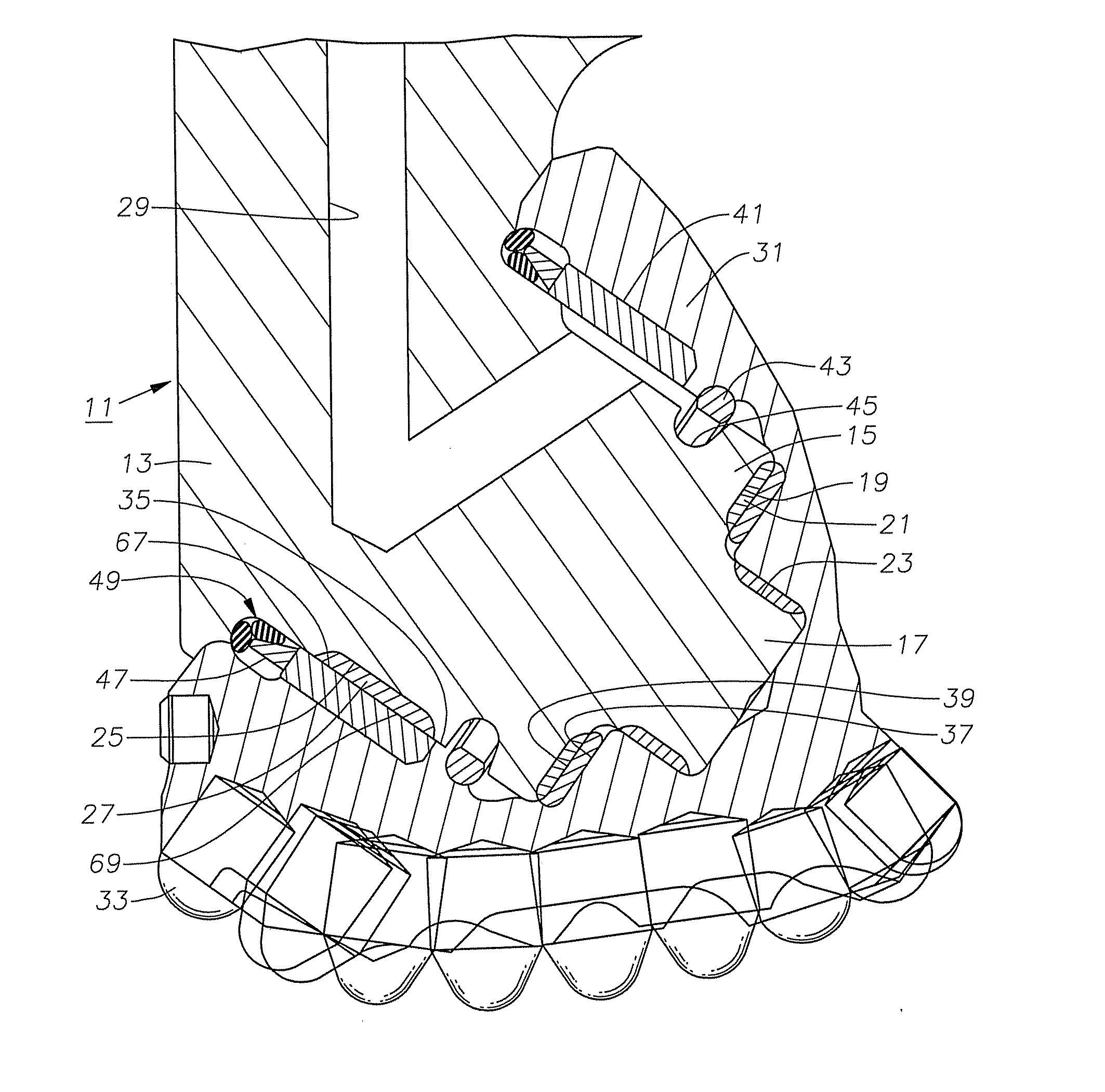
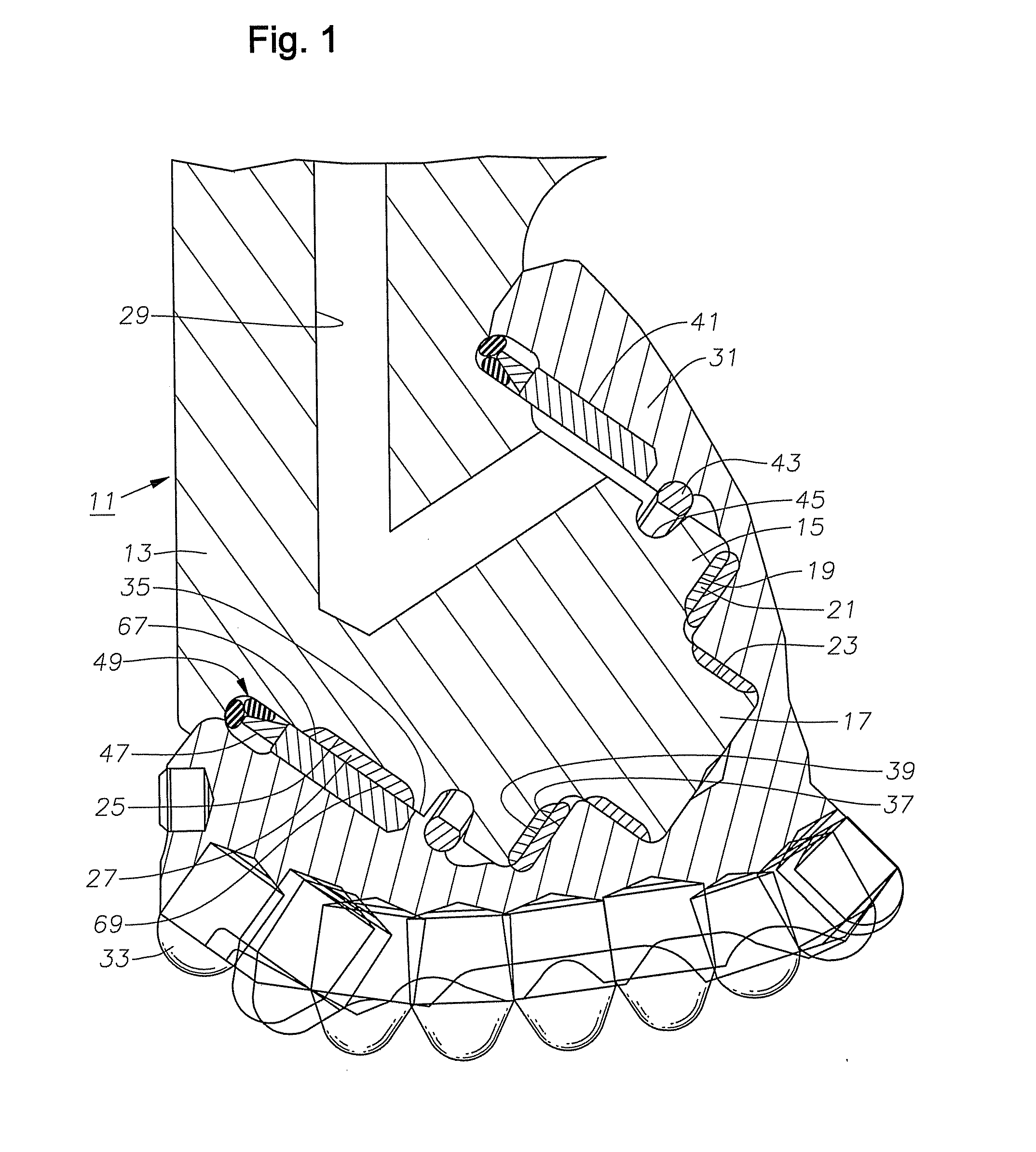
[0043]Referring to FIG. 1, bit 11 has at least one bit leg 13 and normally three. Each bit leg 13 has a bearing pin 15 that extends downward and inward toward an axis of rotation of bit 11. Bearing pin 15 has a cylindrical nose 17 on an inner end that is of lesser diameter than remaining portions of bearing pin 15. An inward facing annular thrust shoulder 19 surrounds nose 17. Thrust shoulder 19 is located in a plane perpendicular to an axis of bearing pin 15. In this embodiment, thrust shoulder 19 optionally has an inlay 21 of a hard, wear resistant material. Similarly nose 17 may have an inlay 23 of the same wear resistant material on its cylindrical exterior.

[0044]Bearing pin 15 has a partially cylindrical journal bearing surface 25 that extends around its lower side. In this embodiment, an optional inlay 27 of a hard wear resistant material is located in journal bearing surface 25. Since the thrust imposed on bit 11 is downward, inlay 27 does not extend to the upper side of bear...


PUM


Abstract

A texture pattern is applied to bearing surfaces of earth-boring bits, especially the bearings of earth boring bits of the roller cutter variety. The textured surface that may be applied to either or both sides of the thrust washer faces, bearing faces, inlays, or thrust shoulders, or a combination thereof.

Description

CROSS-REFERENCE TO RELATED APPLICATION[0001]This application claims priority to provisional application 60 / 812,539, filed Jun. 9, 2006.FIELD OF THE INVENTION[0002]This invention relates in general to earth-boring bits, especially the bearings of earth boring bits of the roller cutter variety. More particularly, the present invention relates to applying a surface texture to improve the performance of the bearings.DESCRIPTION OF THE PRIOR ART[0003]In drilling boreholes in earthen formations by the rotary method, earth-boring bits typically employ at least one rolling cone cutter, rotatably mounted thereon. The bit is secured to the lower end of a drillstring that is rotated from the surface or by downhole motors. The cutters mounted on the bit roll and slide upon the bottom of the borehole as the drillstring is rotated, thereby engaging and disintegrating the formation material. The rolling cutters are provided with teeth that are forced to penetrate and gouge the bottom of the boreho...

Claims


Application Information

Patent Timeline
Patent Type & Authority Applications(United States)
IPC IPC(8): E21B10/00
CPCE21B10/22
Inventor LIN, CHIH C.
Owner BAKER HUGHES INC
Why Eureka
Try Eureka