Molding mold, molding method and tape cartridge

a molding method and mold technology, applied in the direction of printing machines, instruments, magazine/cassette manufacturing apparatus, etc., can solve the problem of inability to maintain the predetermined configuration of the flang

Inactive Publication Date: 2007-12-13
TDK CORPARATION
View PDF9 Cites 3 Cited by
  • Summary
  • Abstract
  • Description
  • Claims
  • Application Information

AI Technical Summary

Benefits of technology

[0008] Another object of the present invention is to provide a tape cartridge provided with a reel hub portion in such that it can securely be prevented that a tape-shaped recording medium wound around a hub of a reel hub portion touches at a flange while the tape cartridge is being used.
[0011] According to the first molding mold, a predetermined configuration of the flange after molding can be maintained even if the reel hub portion has the insert portion, because in the molding surface at the side of the hub forming portion of the flange forming portion, a dimension of a circular area over from the root end near the insert attaching portion to a substantially intermediate portion between the root end and a circumferential end of the flange forming portion, is corrected in view of deformation upon molding.
[0013] According to the second molding mold, a predetermined configuration of the flange after molding can be maintained even if the reel hub portion has the insert portion, because in the molding surface at a side of the hub forming portion of the flange forming portion, a dimension of a circular area over from the root end near the insert attaching portion to a substantially intermediate portion between the root end and a circumferential end of the flange forming portion, is corrected, so that height from the reference position at a side of the insert portion is set to be larger than height before correction of the dimension.
[0016] According to the third molding mold, a predetermined configuration of the flange after molding can be maintained even if the reel hub portion has the insert portion, because in the molding surface between the root end of the hub portion and the circumferential end of the flange portion and in a circular area over from a root end near the insert attaching portion to a substantially intermediate portion between the root end and the circumferential end of the flange forming portion, height from the reference position at the side of the insert portion is gradually reduced from the root end to the circumferential end so that a degree of its reduction is large as compared with that of reduction from the substantially intermediate portion to the circumferential end.
[0021] According to this tape cartridge, it can securely be prevented that the tape-shaped recording medium wound around the hub of the reel hub portion touches at the flange while the tape cartridge is being used, and stable and secure recording and reproducing by the tape-shaped recording medium can be performed because a predetermined configuration of the flange after molding can be maintained as above-mentioned.

Problems solved by technology

Namely, when a metal plate is molded integrally with a reel hub portion by an insert molding, shrinkage in the reel hub portion is obstructed by the insert-molded metal plate at a shrinkage process upon cooling and hardening, resulting in that the inventors obtained the comprehension that a predetermined configuration of the flange cannot be maintained because deformation of the flange occurs upon molding at a portion of the flange especially near the metal plate in comparison with a case without insert-molding.

Method used


Image

  • Molding mold, molding method and tape cartridge
  • Molding mold, molding method and tape cartridge
  • Molding mold, molding method and tape cartridge

Examples


example

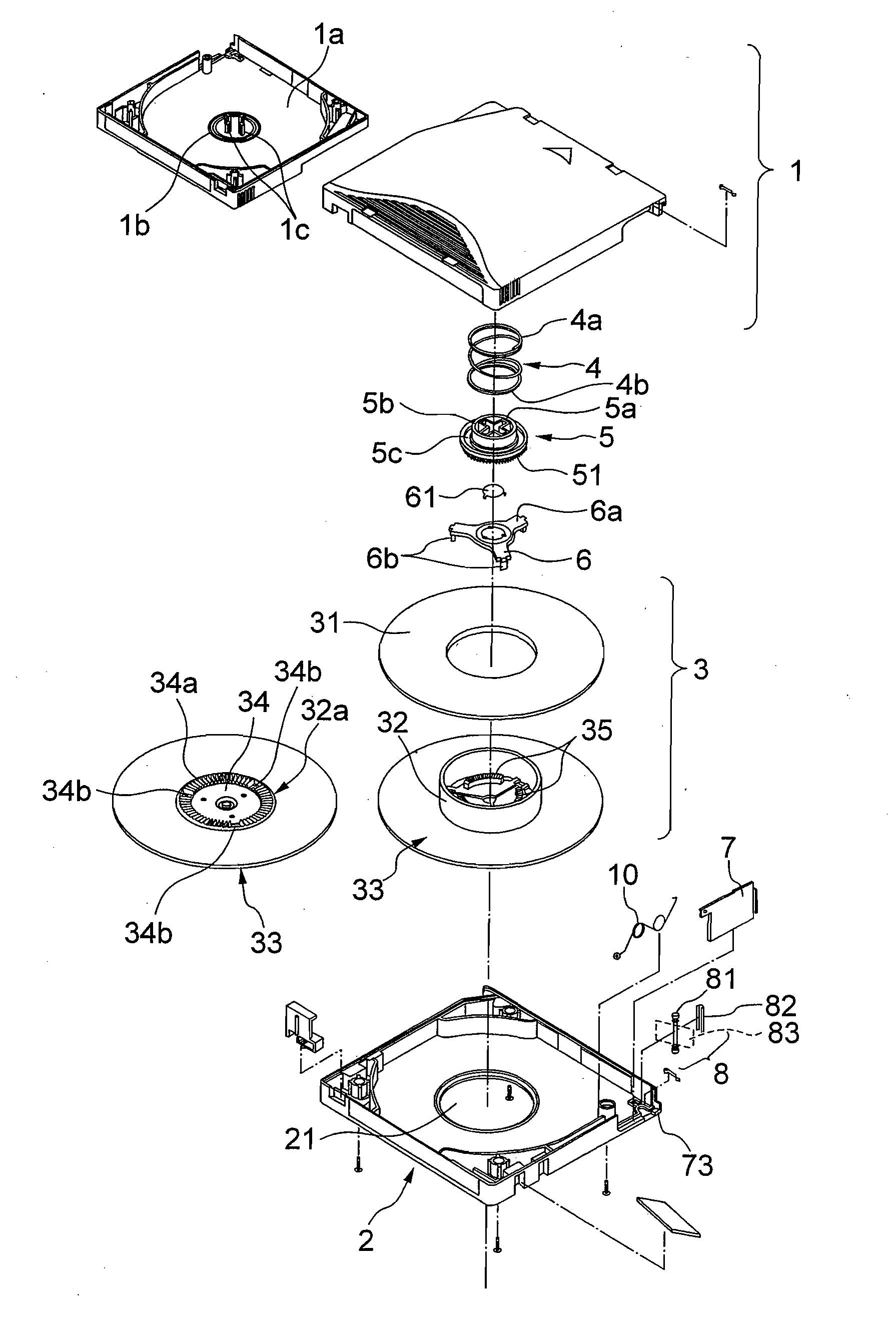
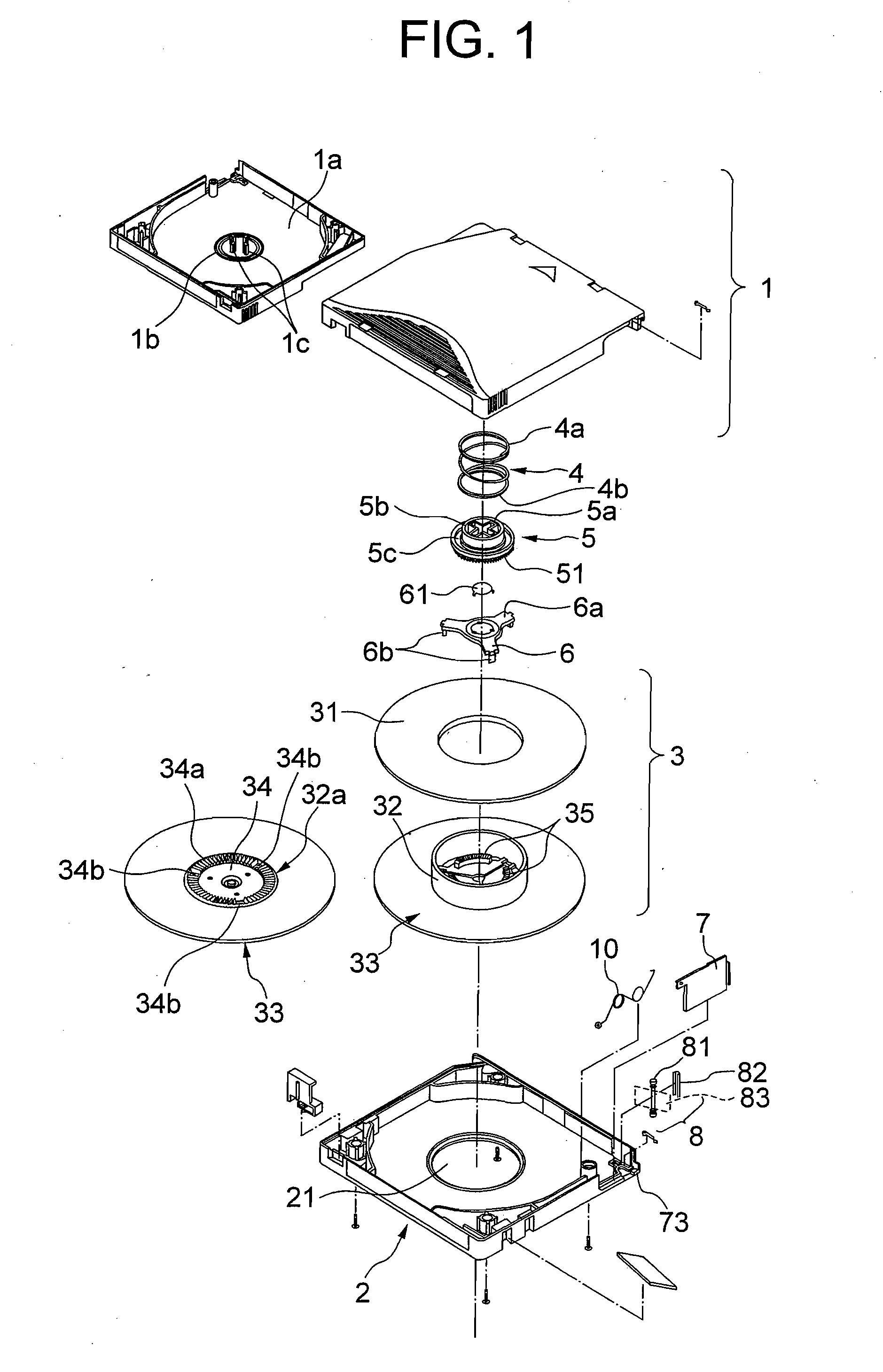
[0064] Next, description will be explained about an example the present invention in more detail. In FIG. 8, as an example, specified dimensions are defined. According to a standard as to a one-reel type tape cartridge for a computer, the height h1 of the root end 33a of the hub 32 in the lower flange 33 from the reference line r is within a range of 1.82 to 2.02 mm while the height h2 of the circumferential end 33b from the reference line r is within a range of 1.66 to 1.90 mm.

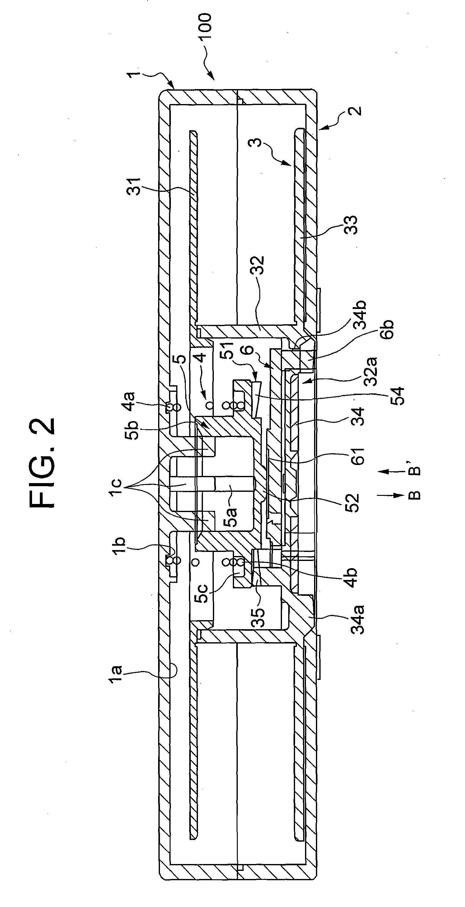
[0065] In the present example, a molding mold 110 as shown in FIG. 5 to FIG. 7 was produced, and a reel hub portion 3 in FIG. 1 (except for the upper flange 31) was molded.

[0066]FIG. 9 is a graph showing the height H of the flat area 106 of the molding mold 110 from the base line R in the present example, in which changing states between the height H before correction and the height H after correction are shown. X-axis of FIG. 9 shows a position in a diameter-direction at the flat area 106, in which ID corr...


PUM

PropertyMeasurementUnit
heightaaaaaaaaaa
height h2aaaaaaaaaa
height h2aaaaaaaaaa

Abstract

A molding mold and a molding method are disclosed, for molding a flange configuration in which a flange of a reel hub portion can be maintained in a predetermined configuration. Also a tape cartridge is disclosed, which can securely prevent a tape-shaped recording medium from touching at the flange while the tape cartridge is being used. In the molding mold for molding, a flange configuration is produced, which is provided with a reel hub portion having a flange and a hub arranged at a substantially center of the flange and an insert portion disposed at a substantially center of the reel hub portion at an opposite side of the hub, and which includes: an insert attaching portion; a flange forming portion for forming the flange; and a hub forming portion for forming the hub; wherein in a forming surface of at a side of the hub forming portion of the flange forming portion, a dimension of a circular area over from a root end of the hub forming portion to a substantially intermediate portion between the root end and a circumferential end of the flange forming portion, is corrected in view of deformation upon molding.

Description

BACKGROUND OF THE INVENTION [0001] 1. Field of the Invention [0002] The present invention relates to a molding mold and a molding method for molding a flange configuration, and a tape cartridge. [0003] 2. Description of the Prior Art [0004] A one-reel-type cartridge is provided with a reel hub portion having an upper flange and a lower flange at an inside of the cartridge. A tape-shaped recording medium is wound around the hub portion, which is used for storing back-up data for a computer or the like. When the tape cartridge is mounted to a magnetic recording and reproducing apparatus for a computer, the tape-shaped recording medium wound around a hub of an internal reel hub portion is made to be drawn out, and thereafter wound around a reel hub portion at the side of the magnetic recording and reproducing apparatus, so that the tape-shaped recording medium runs between both the hubs, and recording or reproducing are performed. Also, a magnetic plate is attached to a center of the l...

Claims


Application Information

Patent Timeline
Patent Type & Authority Applications(United States)
IPC IPC(8): G11B15/32B29C33/38B29C45/00G11B23/107B29C45/14B29C45/26G11B23/087G11B23/113
CPCB29C33/3835B29C45/0025B29C45/1459G11B23/08785B29C45/2616G11B23/08728B29C45/26
Inventor SATOH, TAKATERUSUZUKI, HIROKIMOMOI, AKIO
Owner TDK CORPARATION
Why Eureka
Try Eureka