Driving circuit and liquid crystal display device including the same

a driving circuit and liquid crystal display technology, applied in the direction of circuit inspection/indentification, instruments, optics, etc., can solve the problems of deteriorating display quality of the lcd device, reducing fabrication yield, and difficult to attach the driving circuit to the array substrate, so as to improve picture quality, improve alignment, and increase fabrication yield

Active Publication Date: 2007-12-13
LG DISPLAY CO LTD
View PDF2 Cites 10 Cited by
  • Summary
  • Abstract
  • Description
  • Claims
  • Application Information

AI Technical Summary

Benefits of technology

[0016]An object of the present invention is to provide a liquid crystal display device with improved alignment between tape carrier packages and the liquid crystal panel.
[0017]Another object of the present invention is to provide a liquid crystal display device with improved picture quality, increased fabrication yield, and reduced production cost.

Problems solved by technology

However, as the size of the LCD device increases, it becomes more difficult to attach the driving circuit to the array substrate.
However, the first and second TCP alignment marks 41a and 41b may not be properly aligned with the first and second panel alignment marks 42a and 42b due to an accumulated alignment error during the fabrication process.
The misalignment causes deterioration in display quality of the LCD device.
In addition, since the misaligned TCP and the liquid crystal panel need to be re-attached, fabrication yield is reduced and production cost increases.

Method used


Image

  • Driving circuit and liquid crystal display device including the same
  • Driving circuit and liquid crystal display device including the same
  • Driving circuit and liquid crystal display device including the same

Examples


Embodiment Construction

[0032]Reference will now be made in detail to the preferred embodiments of the present invention, examples of which are illustrated in the accompanying drawings.

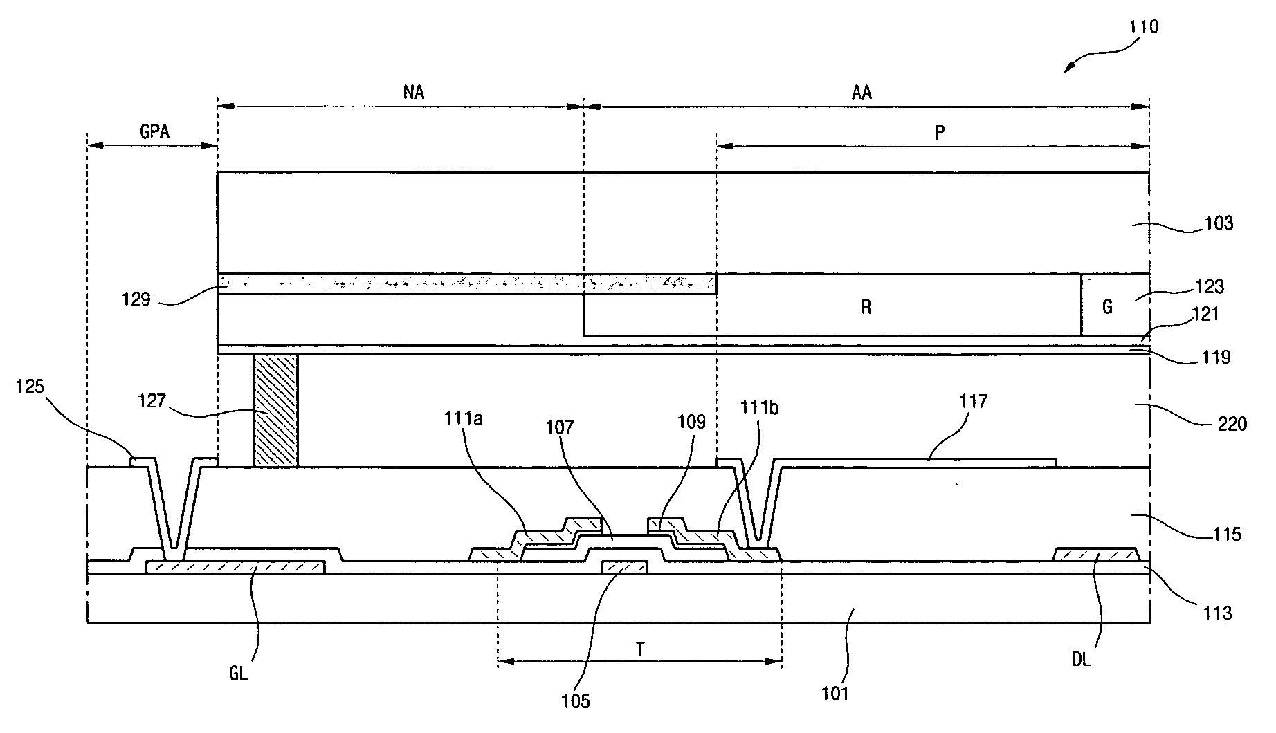
[0033]FIG. 4 is a schematic cross-sectional view showing a liquid crystal panel for a liquid crystal display (LCD) device according to an embodiment of the present invention.

[0034]As shown in FIG. 4, a liquid crystal panel 110 includes a first substrate 101, a second substrate 103 facing the first substrate 101, and a liquid crystal layer 220 between the first and second substrates 101 and 103. The liquid crystal panel 110 includes a display area “AA” for displaying images and a non-display area “NA” at a periphery of the display area AA. A plurality of gate pads 125 and a plurality of data pads (not shown) are formed in a gate pad portion “GPA” and a data pad portion (not shown), respectively, in the non-display area NA on the first substrate 101. In addition, a gate line “GL” and a gate electrode 105 are formed on the firs...


PUM


Abstract

A tape carrier package (TCP) includes a film, a plurality of output leads and a plurality of input leads on the film, the plurality of output leads and the plurality of input leads being disposed on different sides, first and second TCP alignment marks arranged on opposing sides of the plurality of output leads, and a third TCP alignment mark at a central portion of the plurality of output leads.

Description

[0001]This application claims the benefit of the Korean Patent Application No. 2006-0050852 filed on Jun. 7, 2006, which is hereby incorporated by reference.BACKGROUND OF THE INVENTION[0002]1. Field of the Invention[0003]The present invention relates to a liquid crystal display (LCD) device, and more particularly to a driving circuit for driving the same.[0004]2. Discussion of the Related Art[0005]A liquid crystal display (LCD) device includes an array substrate, a color filter substrate facing and spaced apart from the array substrate, and a liquid crystal layer disposed between the array substrate and the color filter substrate. The array substrate includes a gate line and a data line crossing each other. A thin film transistor (TFT) is connected to the gate line and the data line. The color filter substrate includes a color filter layer and a common electrode.[0006]The LCD device further includes a driving circuit. The driving circuit may be connected to the array substrate accor...

Claims


Application Information

Patent Timeline
Patent Type & Authority Applications(United States)
IPC IPC(8): H01L23/544
CPCG02F1/13452H01L23/49838H01L23/4985H01L23/544H01L2223/54426H05K1/0269H05K3/361H01L2924/0002H05K2201/09918H05K2201/10681H05K2203/166H01L2924/00G02F1/1345
Inventor KIM, MIN-HWAHONG, JIN-CHEOL
Owner LG DISPLAY CO LTD
Why Eureka
Try Eureka