Passive Power Combiner for Dual Power over Ethernet Sources

a dual-load, ethernet-based technology, applied in the direction of dc network circuit arrangement, dc source parallel operation, transportation and packaging, etc., can solve the problems of dual-load pd and two ps

Inactive Publication Date: 2007-12-13
ROBBINS STEVEN ANDREW
View PDF3 Cites 61 Cited by
  • Summary
  • Abstract
  • Description
  • Claims
  • Application Information

AI Technical Summary

Benefits of technology

[0007]Accordingly, it is a principle objective of the present invention to overcome the disadvantages of prior art. This is provided in the present invention by a method and apparatus for passively combi

Problems solved by technology

The IEEE standard places a limit on the maximum power that can be delivered to a PD on a single Ethernet cable, and this limit has been an impediment to some new PoE application that require mor

Method used


Image

  • Passive Power Combiner for Dual Power over Ethernet Sources
  • Passive Power Combiner for Dual Power over Ethernet Sources
  • Passive Power Combiner for Dual Power over Ethernet Sources

Examples


Embodiment Construction

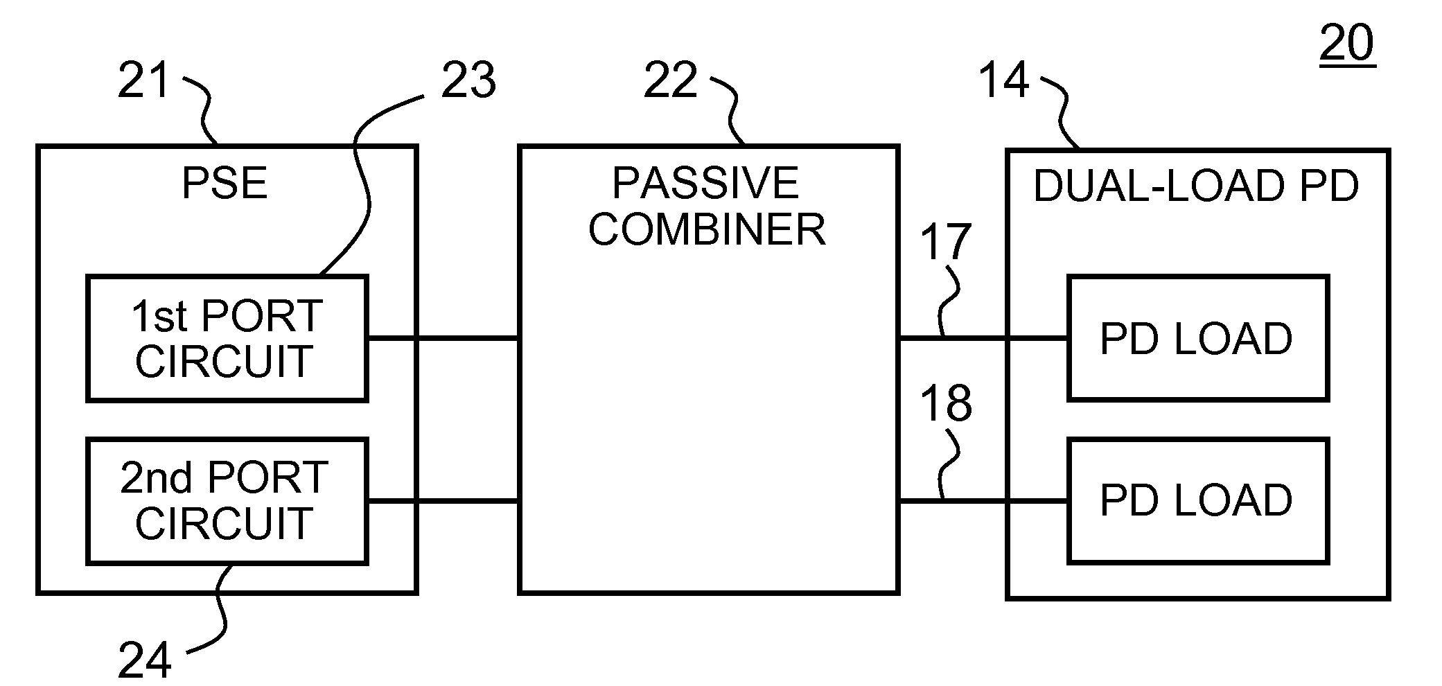
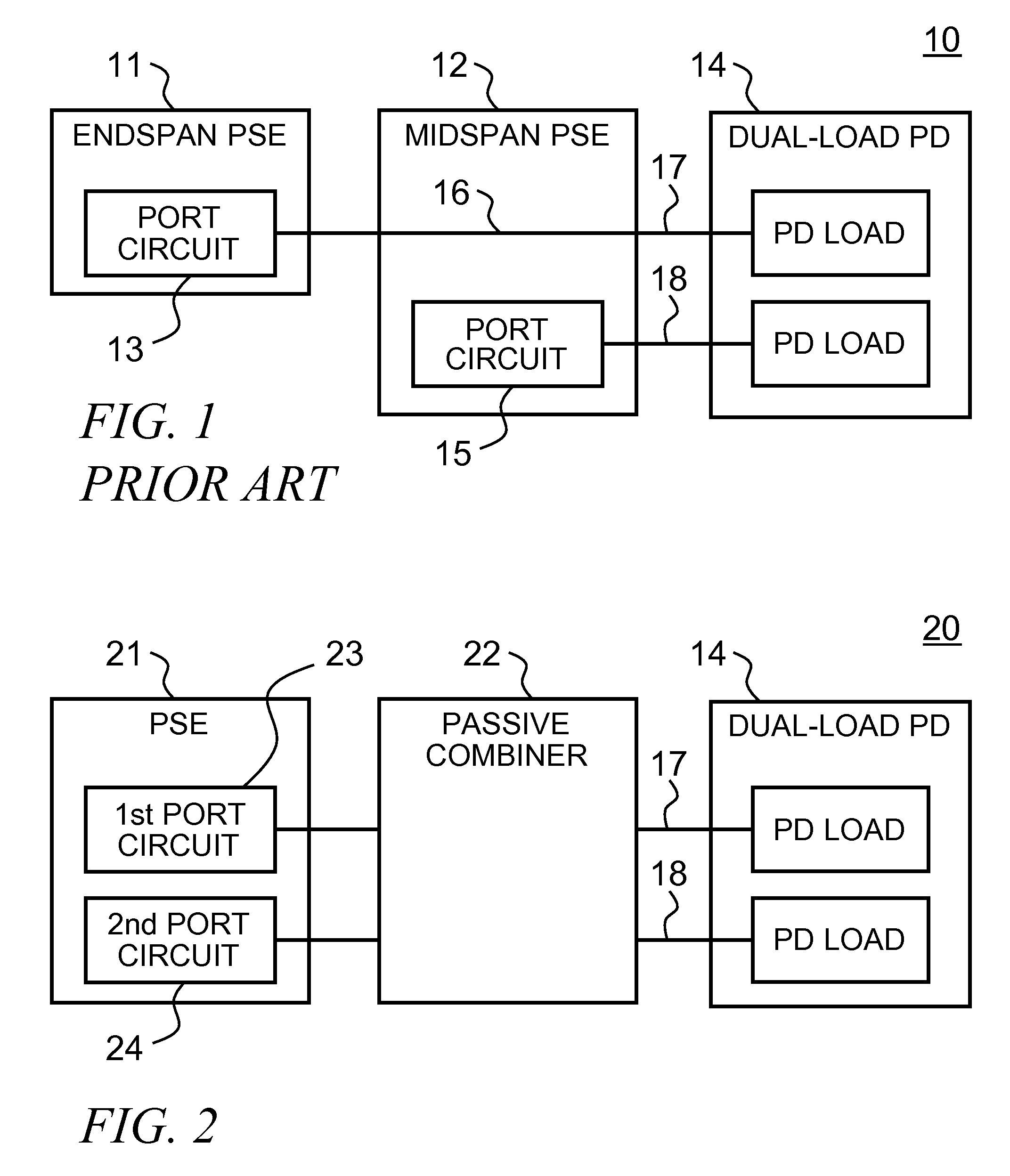
[0022]FIG. 2 shows a novel system 20 in accordance with the teachings of the invention. A passive combiner apparatus 22 interfaces to two ports 23 and 24 on the same PSE 21, and combines their outputs onto a single cable such that the first PSE port 23 supplies power to the dual-load PD 14 on the Alt-A pairs 17, and the second PSE port 24 supplies power to the dual-load PD 14 on the Alt-B pairs 18. This allows the dual-load PD 14 to be fully powered without the expense of purchasing two PSE. The PSE 21 can be either an endspan or a midspan.

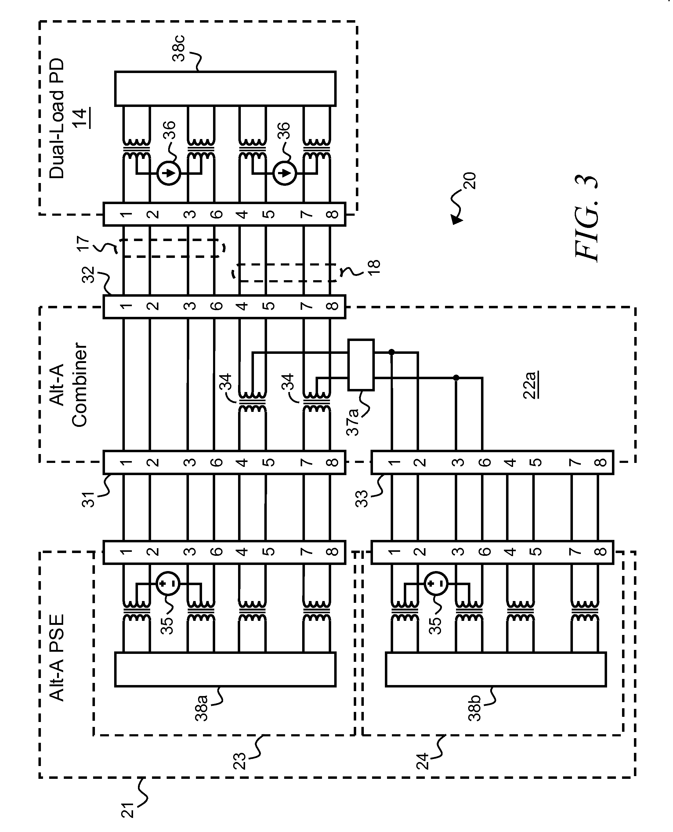
[0023]FIG. 3 shows a simplified schematic diagram that reveals portions of the system 20 of FIG. 2 in greater detail. Purely for the purpose of example, all the connectors shown in all the figures are assumed to be of the RJ45 type and the pin numbers shown are as defined in the IEEE standard; thus the Alt-A wires 17 connect with pins 1, 2, 3, and 6 on the RJ45 connectors; and the Alt-B wires 18 connect with pins 4, 5, 7 and 8 on the RJ45 connecto...


PUM


Abstract

The invention includes a method and apparatus, each with several embodiments, for combining power from two ports of a multi-port Power Sourcing Equipment (PSE) for Power over Ethernet (PoE) systems, for the purpose of providing increased power to a Powered Device (PD) that comprises two separate loads and requires two sources of power.

Description

CROSS-REFERENCE TO RELATED APPLICATIONS[0001]This application claims priority from U.S. Provisional Patent Application No. 60804434 titled A Passive Combiner for PoE Power Sources, filed on Jun. 10, 2006.TECHNICAL FIELD OF THE INVENTION[0002]The invention relates generally to the field of Power over Ethernet (PoE)—a system that provides limited DC power over computer networking cables—and more specifically to the subject of providing increased power for PoE applications.BACKGROUND OF THE INVENTION[0003]The IEEE issued an amendment to IEEE Std 802.3™-2002; this amendment, titled Data Terminal Equipment (DTE) Power via Media Dependent Interface (MDI), was published as IEEE Std 802.3af™-2003, and is hereinafter referred to as the “IEEE standard”. The IEEE standard, whose contents are incorporated herein by reference, is commonly referred to as Power over Ethernet (PoE), and specifies methods and requirements for delivery of limited DC power using two of the four twisted-pairs contained...

Claims


Application Information

Patent Timeline
IPC IPC(8): H02J1/00
CPCH02J13/0062H02J1/10H02J13/00016
Inventor ROBBINS, STEVEN ANDREW
Owner ROBBINS STEVEN ANDREW
Why Eureka
Try Eureka