Supercharge Your Innovation With Domain-Expert AI Agents!

Dual field of view lens system

a lens system and dual field of view technology, applied in the field of optical lens systems, can solve the problems of insufficient robustness of the typical commercial zoom and focus lens mechanism, the inability to repair or replace the failure of the commercial lens system, and the increase of the cost, volume and mass of having multiple cameras and lens systems

Inactive Publication Date: 2007-12-13
THE BOEING CO
View PDF11 Cites 3 Cited by
  • Summary
  • Abstract
  • Description
  • Claims
  • Application Information

AI Technical Summary

Benefits of technology

The present invention is about a special lens system that can capture two different fields of view simultaneously. The lens system has two groups of lenses that are aligned along the optical axis. The first group is positioned close to the camera, while the third group is positioned a certain distance from the first group. The second group of lenses is positioned between the first and third groups and can move along the optical axis to capture either a wide or narrow field of view. The lens system also has an optical stop that helps to control the amount of light that enters the lens system. The technical effect of this invention is that it allows for a more versatile and flexible lens system that can capture both wide and narrow field of views with ease.

Problems solved by technology

However, one problem with these system is that typical commercial zoom and focus lenses have mechanisms that are not sufficiently robust for these lenses.
Some disadvantages to this approach are the increased cost, volume, and mass of having multiple cameras and lens systems.
One disadvantage to this approach is that a failing commercial lens system cannot be repaired or replaced in unmanned situations and these lens systems tend to mechanically fail due to shock, extreme changes in temperature, etc.
Attempting to make these types of lens systems more robust makes these lens systems tend to be large and complicated (e.g. most lens systems require three or more independent lens group motions to operate).
There have been single motion zoom lens systems used previously, however, these systems have been used for infrared systems and the image quality has not been suitable for visible light applications.

Method used


Image

  • Dual field of view lens system
  • Dual field of view lens system
  • Dual field of view lens system

Examples


Embodiment Construction

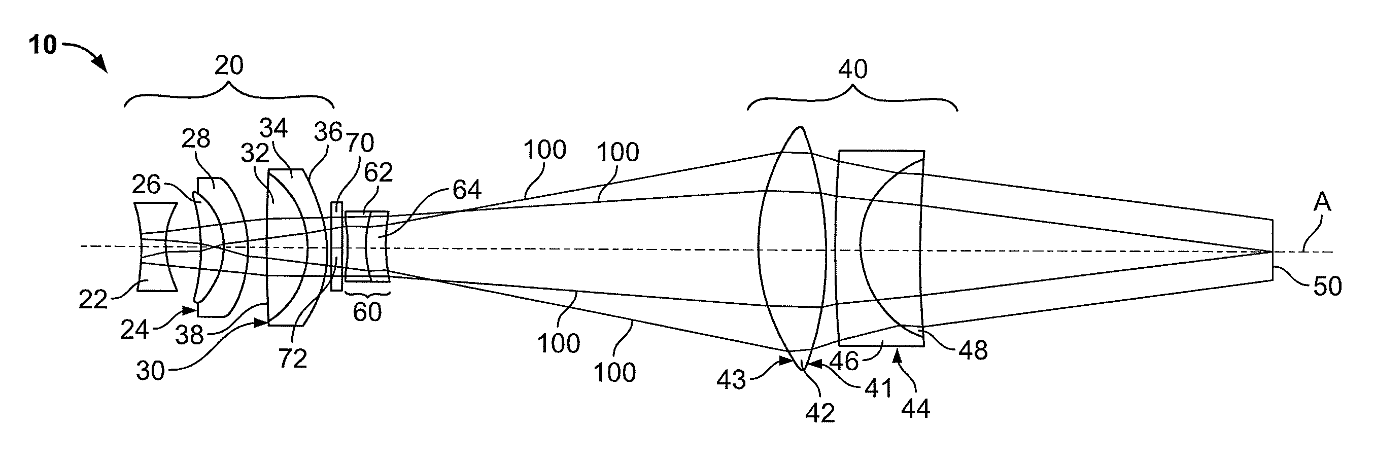
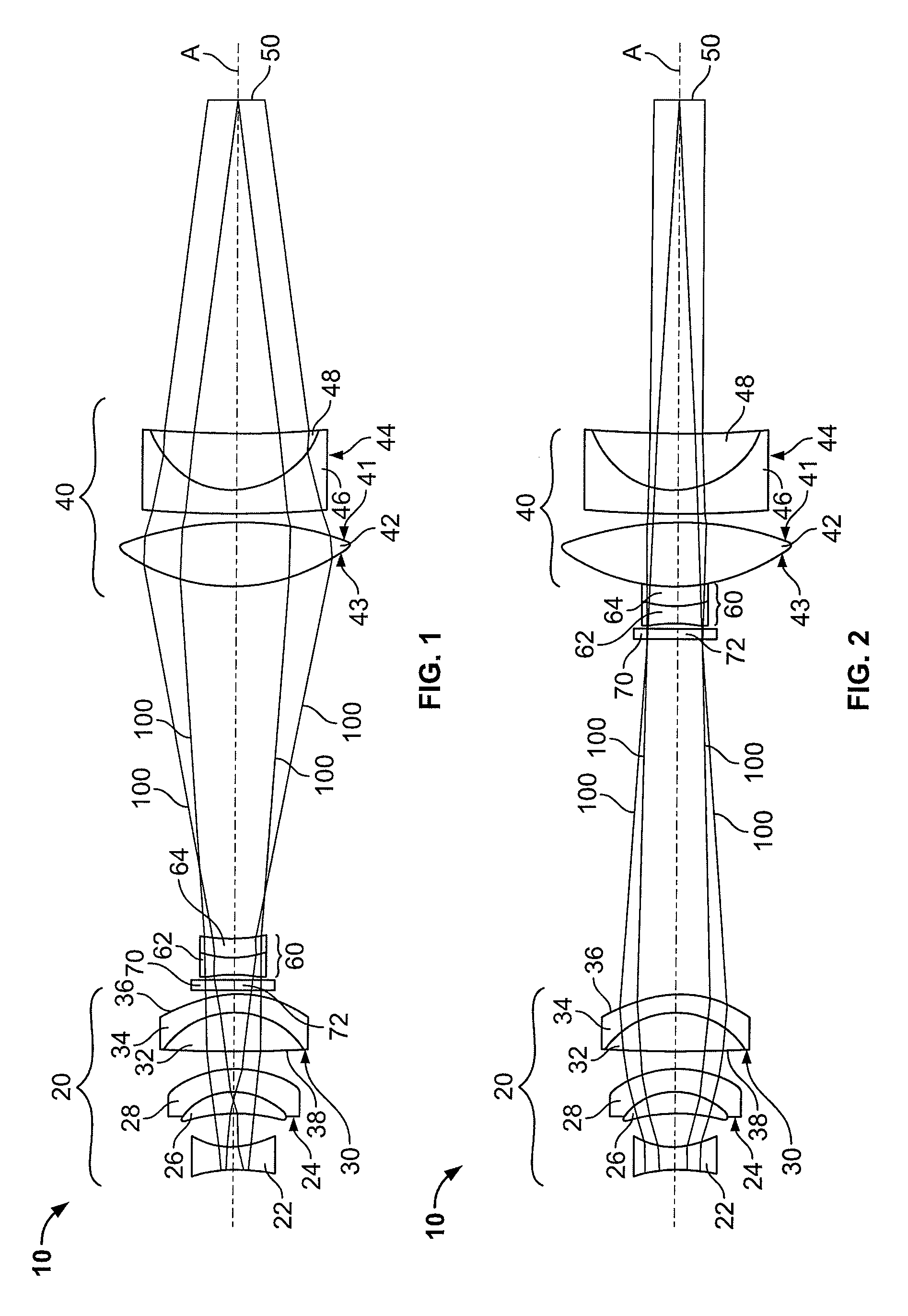
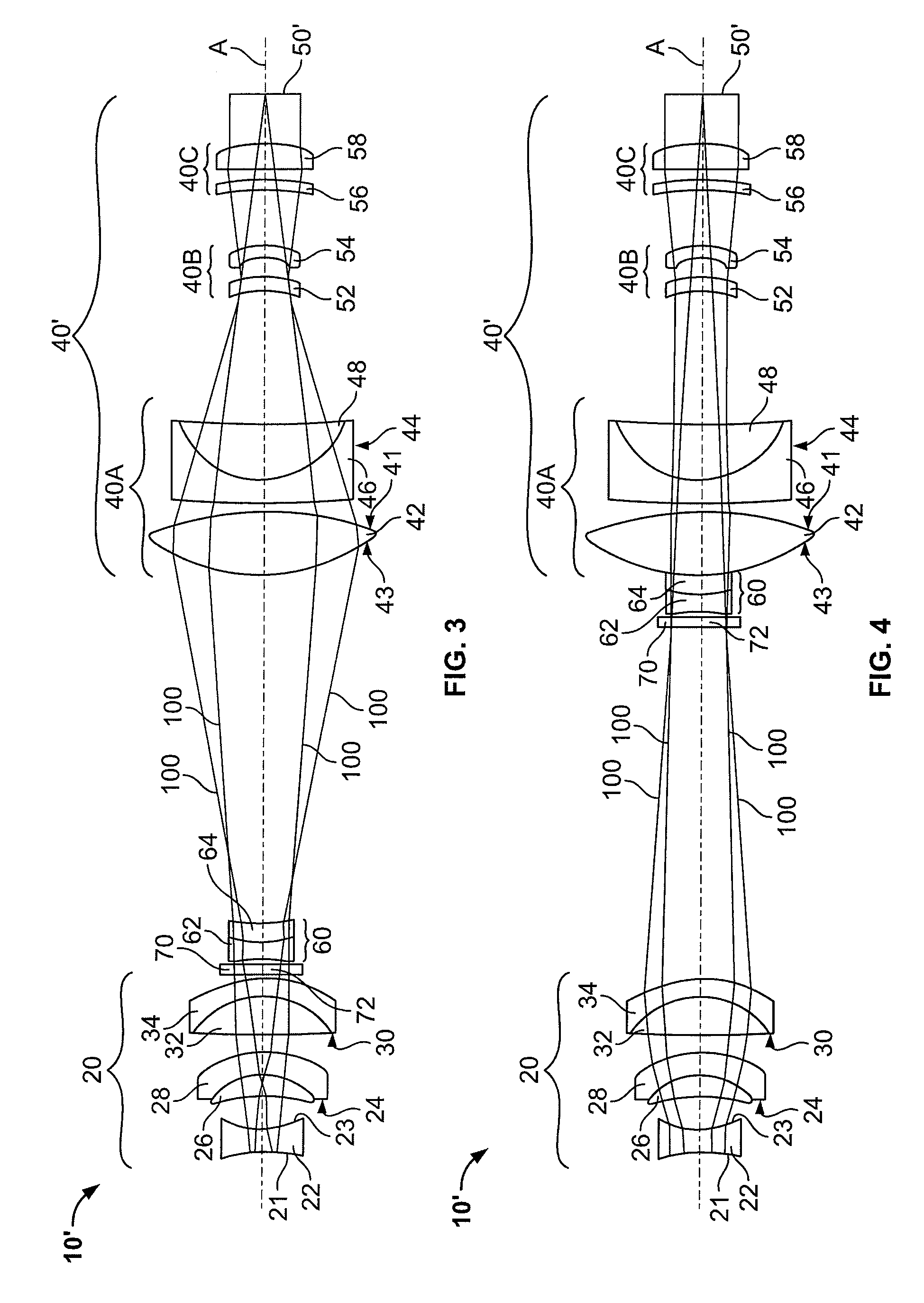
[0014]Referring to FIGS. 1 and 2, an exemplary dual field of view zoom lens system 10 is shown. In the example shown, the system 10 generally has a first lens group 20, a second lens group 60, a third lens group 40, and an optical stop 70. As is well known in the art, each lens “group” can consist of a single lens or can be made up of multiple lenses, depending on the usage and requirements of the system.

[0015]First and third lens groups 20, 40 are aligned along an optical axis A and their positions relative to each other and to focal plane 50 are fixed. Second lens group 60 is aligned along optical axis A between first lens group 20 and third lens group 40 and is movable linearly between a first position (shown in FIG. 1) and a second position (shown in FIG. 2), for example through a linear drive screw, a worm-gear device with a stepper motor, or any other well know device for providing linear motion to a lens group. Optical stop 70 is connected to second lens group 60 such that op...


PUM


Abstract

A dual field of view lens system comprising a first lens group aligned along an optical axis and a third lens group aligned along the optical axis and positioned a predetermined distance from the first lens group. A second lens group, having an optical stop attached thereto, is aligned along the optical axis and disposed between the first and third lens group such that the second lens group and the optical stop are moveable along the optical axis between a first position and a second position. Positioning the second lens group and the optical stop in the first position provides a wide field of view and moving the second lens group and the optical stop to a second position provides a narrow field of view.

Description

FIELD OF THE INVENTION[0001]This invention relates generally to optical lens systems and in particular to a dual field of view lens system.BACKGROUND[0002]In lens systems for military, marine, industrial, outer space, or other rugged use, various machine vision systems having zoom and focus capability are used. However, one problem with these system is that typical commercial zoom and focus lenses have mechanisms that are not sufficiently robust for these lenses.[0003]One possible solution is to use multiple cameras and lens systems instead of using one lens system. Some disadvantages to this approach are the increased cost, volume, and mass of having multiple cameras and lens systems.[0004]Another possible solution is to use standard commercial lens systems that have mechanical devices to zoom the lens. One disadvantage to this approach is that a failing commercial lens system cannot be repaired or replaced in unmanned situations and these lens systems tend to mechanically fail due...

Claims


Application Information

Patent Timeline
Patent Type & Authority Applications(United States)
IPC IPC(8): G02B9/12
CPCG02B15/177G02B15/143105
Inventor LUNDGREN, MARK A.
Owner THE BOEING CO
Features
  • R&D
  • Intellectual Property
  • Life Sciences
  • Materials
  • Tech Scout
  • Unparalleled Data Quality
  • Higher Quality Content
  • 60% Fewer Hallucinations
Learn More