Combined X-Ray CT/Neutron Material Identification System

a material identification and ct technology, applied in the field of combined x-ray ct/neutron material identification system, can solve problems such as overflowing airport cargo flow

Inactive Publication Date: 2007-12-13
AMERICAN SCI & ENG INC
View PDF14 Cites 15 Cited by
  • Summary
  • Abstract
  • Description
  • Claims
  • Application Information

AI Technical Summary

Problems solved by technology

It is therefore quite likely that for a typical air cargo container, several items in the container will have a density that lies in the density range of explosives, and false alarms would thus overwhelm airport cargo flow.

Method used


Image

  • Combined X-Ray CT/Neutron Material Identification System
  • Combined X-Ray CT/Neutron Material Identification System
  • Combined X-Ray CT/Neutron Material Identification System

Examples


Embodiment Construction

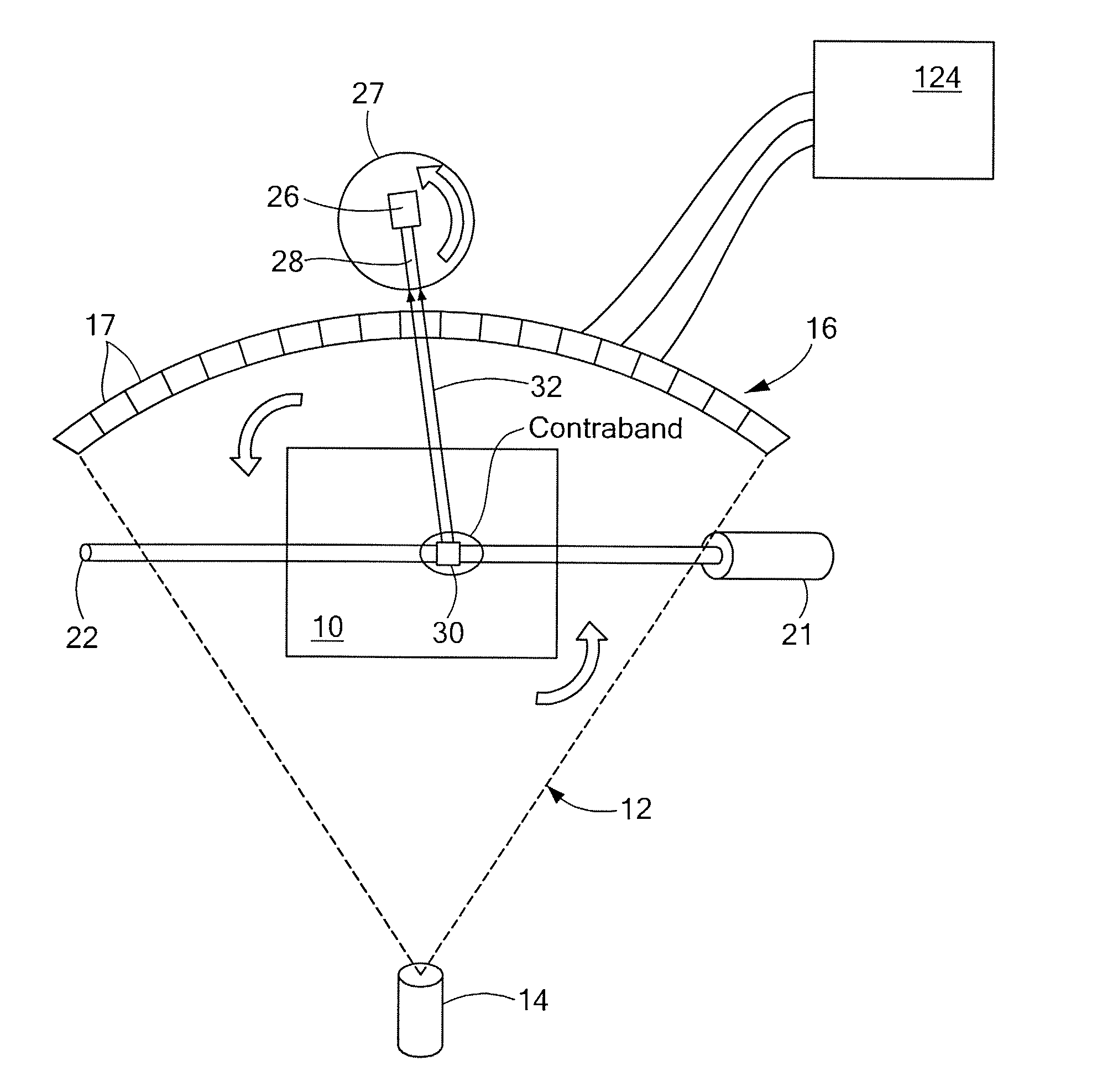
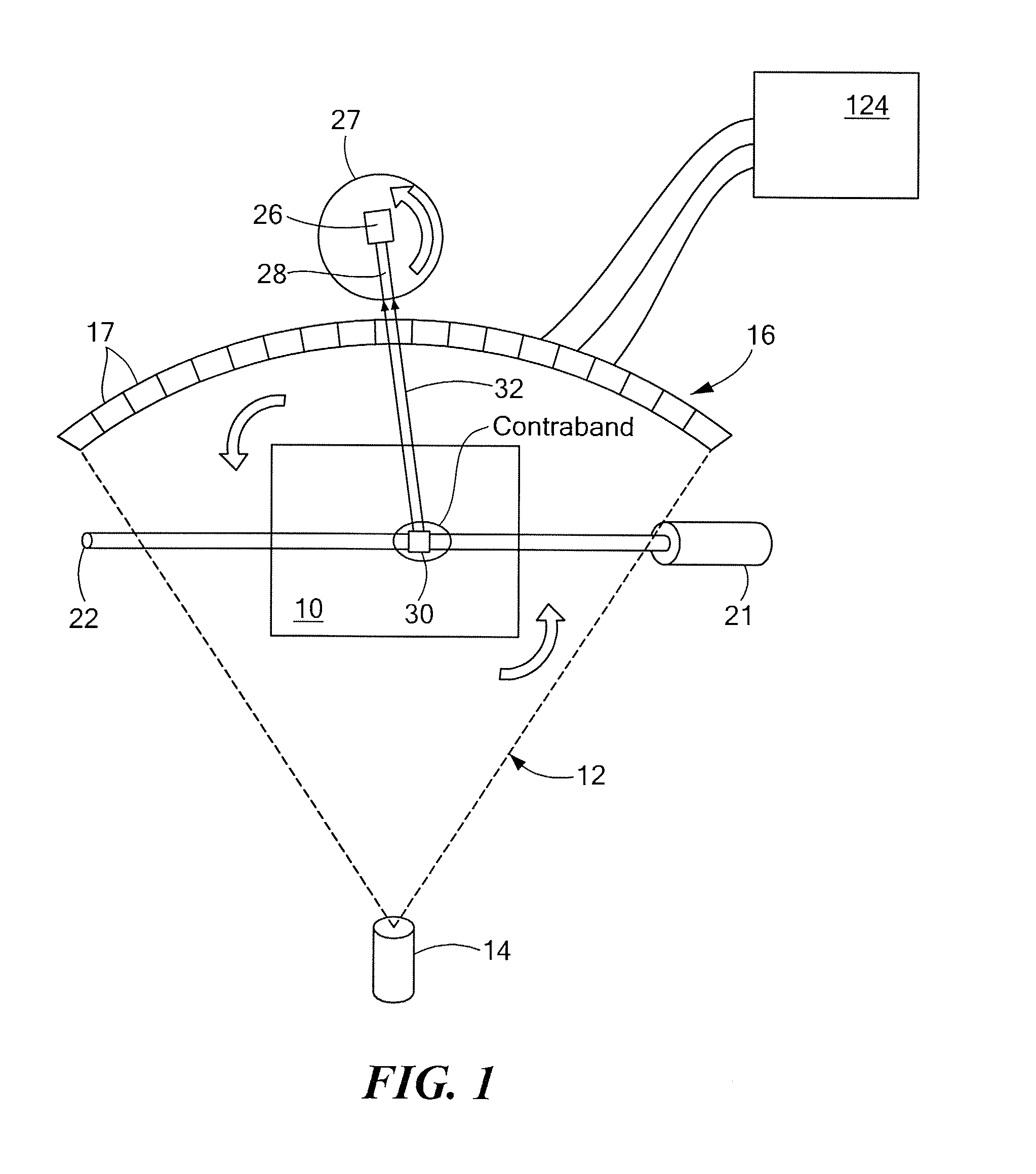
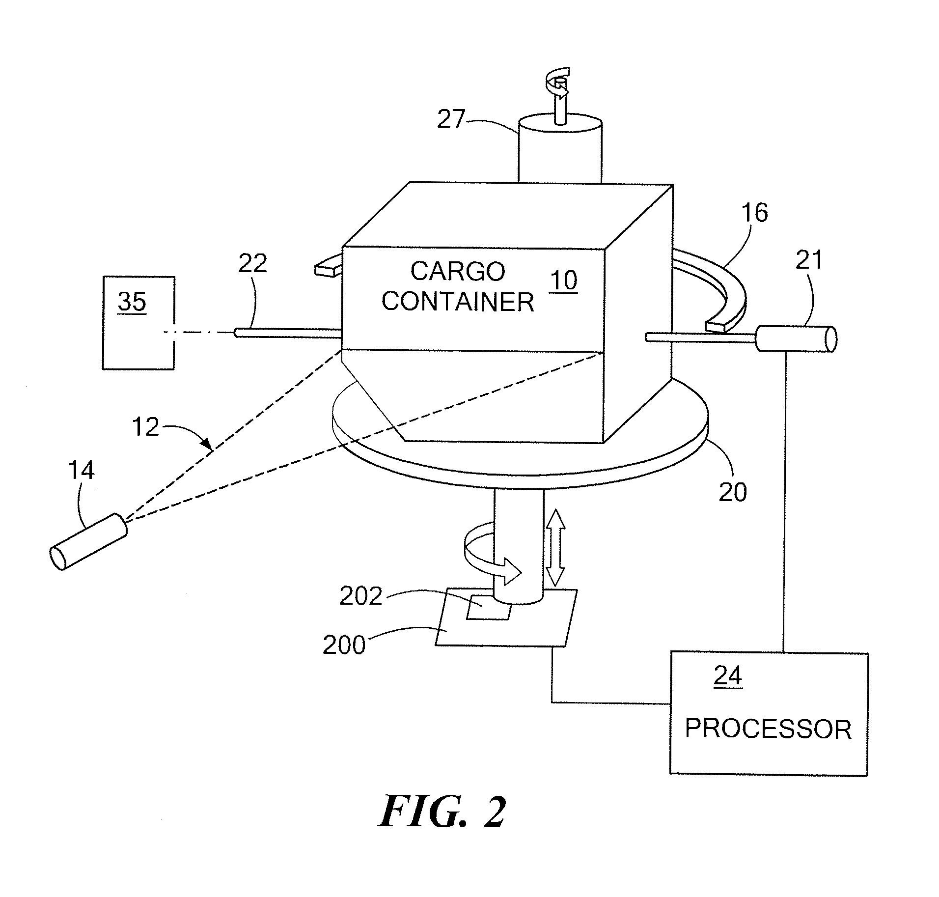
[0019]In accordance with preferred embodiments of the present invention, a method is provided for using an X-Ray CT system as the level one system, combined with a level two system that uses energetic neutrons to perform specific material identification. Even if the false alarm rate of the x-ray CT system (the “level one” system) approaches unity, if the x-ray CT system is followed with a second “level two” system which is able to resolve these false alarms, then the false alarm rate of the combined system may be reduced to the false alarm rate of the level two system. By using a level two system which is able to identify the actual elemental makeup of the suspect material identified by the level one system, very low false alarm rates can be achieved, while not compromising the detection rate of the combined system.

[0020]The x-ray CT system may measure density of materials, with density serving as a criterion for identifying potential threat materials to be subjected to the next lev...


PUM

PropertyMeasurementUnit
energyaaaaaaaaaa
energyaaaaaaaaaa
energyaaaaaaaaaa

Abstract

Combined X-Ray CT/Neutron Material Identification System A system and methods for identifying contents of an enclosure such as an air cargo container. A three-dimensional image indicative of at least one of the CT number and the density of contents of the enclosure is obtained using penetrating radiation such as x-rays. If one or more suspect regions are identified among contents of the enclosure, a collimated neutron beam is activated to traverse each suspect region and fluorescent emission from the suspect region is detected, allowing material within the suspect region to be characterized based at least on the detected fluorescent emission. Additionally, the collimated neutron beam may be employed for neutron imaging of the contents of the enclosure.

Description

[0001]The present application claims the priority of U.S. Provisional Patent Application Ser. No. 60 / 798,159, which was filed May 5, 2006, and which is incorporated herein by reference.TECHNICAL FIELD [0002]The present invention relates to methods and systems for the use of x-ray computer tomography in combination with neutron-activated gamma ray spectroscopy for inspection of materials.BACKGROUND OF THE INVENTION [0003]X-ray Computerized Tomography (CT) is currently the only automated explosive detection technique for the aviation industry that has been certified by the United States Government. The technique involves taking x-ray images at many different angles through an object and using mathematical reconstruction algorithms (such as filtered back-projection) to reconstruct tomographic slices through the object. These slices can then be combined to form a three-dimensional model of the object. In particular, the method allows the density of organic materials concealed inside the...

Claims


Application Information

Patent Timeline
Patent Type & Authority Applications(United States)
IPC IPC(8): G01N23/05G01N23/04
CPCG01N23/046G01N23/223G01T1/2985G01N2223/419G01V5/005G01N2223/076G01V5/0033G01V5/0069
Inventor ROTHSCHILD, PETER J.
Owner AMERICAN SCI & ENG INC
Why Eureka
Try Eureka