Air cargo vertical restraint assembly

a technology for cargo and assembly, applied in the field of vertical restraints, can solve the problems of structural damage, danger of being struck by a heavily loaded cargo container, and damage to the cargo container (and sometimes, the cargo therein)

Active Publication Date: 2007-04-19
THE BF GOODRICH CO
View PDF7 Cites 4 Cited by
  • Summary
  • Abstract
  • Description
  • Claims
  • Application Information

AI Technical Summary

Problems solved by technology

One of the challenges confronting operators of freighter aircraft is efficiently handling cargo to be transported by the aircraft.
These powered cargo container handling systems require some means of guiding the heavy cargo containers to their proper destination in the cargo compartment, while preventing them from striking the side walls of the aircraft and possibly doing structural damage as they are being loaded or unloaded.
If a guide stop for narrow containers is inadvertently left in place, it is in danger of being...

Method used


Image

  • Air cargo vertical restraint assembly
  • Air cargo vertical restraint assembly
  • Air cargo vertical restraint assembly

Examples


Embodiment Construction

[0036] The contents of aforementioned U.S. Pat. No. 5,692,862 are incorporated by reference to the extent necessary to understand the present invention.

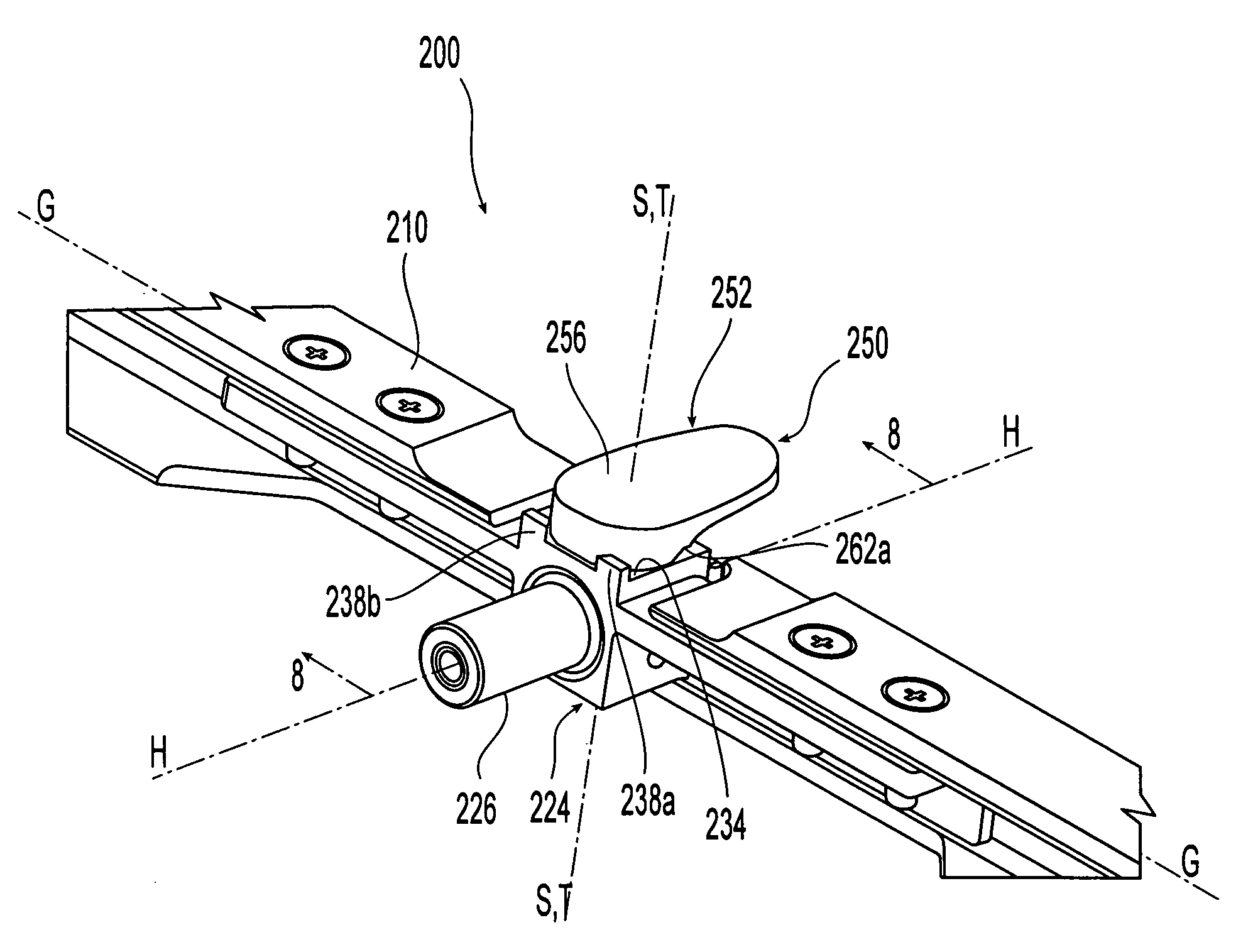
[0037]FIG. 2 shows an exploded view, and FIG. 3 shows an assembled view of a vertical restraint and guide rail assembly 200 in accordance with the present invention. The retracting rail support has been omitted for simplicity in these two figures, it being understood that a variety of such retracting rail supports may be used in conjunction with the present invention, so long as they are appropriately mated to guide rail assembly 200 (or its handle member 226). Also, only a portion of the guide rail assembly is shown, it being understood that the structures described below may be repeated along the length of the guide rail.

[0038] The assembly 200 comprises a guide rail 210, one or more vertical restraint support brackets 220, and a vertical restraint member 250 associated with each vertical restraint support bracket 220.

[0039] The...


PUM


Abstract

A vertical restraint and guide rail assembly includes a number of features which individually, or collectively, may be implemented to enhance performance. One such feature is a vertical restraint head whose forwardmost point is laterally offset from a longitudinal axis A that passes through the pivot point. A second feature is a vertical restraint head having radiused bottom surface, the lowest point of the bottom surface being aligned with the longitudinal axis A even though the forwardmost point of the vertical restraint head is laterally offset from this axis. Another feature is a pair of stops formed on the housing in which the shaft of the vertical restraint member is rotatably mounted. The stops limit rotation of the vertical restraint member to thereby reduce fatigue or hysteresis of the spring mechanism that provides a resisting force when the vertical restraint member has been deflected in either rotational direction. Yet another feature is a pair of spaced apart spring actuation bosses formed on an inner side wall of a housing bore, the spring actuation bosses comprising circumferential abutment surfaces which serve as stops for opposing side edges of a leaf spring.

Description

CROSS REFERENCE TO RELATED APPLICATIONS [0001] None. BACKGROUND OF THE INVENTION [0002] The present invention is related to a vertical restraint of the sort attached to a guide rail mounted on a floor of an aircraft cargo compartment. [0003] One of the challenges confronting operators of freighter aircraft is efficiently handling cargo to be transported by the aircraft. Early freighters used manual labor to load and unload cargo. The loading and unloading operation has been improved dramatically by using large cargo containers designed to fit within the space limitations of an aircraft cargo compartment. Many items of freight headed for a single destination are loaded into a single container and then transported to the aircraft as a single unit rather than being transported as individual items of freight. [0004] Aircraft cargo handling systems have been developed to move these cargo containers once they have been transported to the aircraft. For example, the cargo compartment deck s...

Claims


Application Information

Patent Timeline
IPC IPC(8): B60P1/64
CPCB64D9/003
Inventor BREKKEN, GREGORY ALBERTNIEMEIER, RODNEY ORLANDLARSON, WALLACE HAROLD
Owner THE BF GOODRICH CO
Why Eureka
Try Eureka