Bookbinding device and image forming apparatus

a technology of image forming apparatus and bookbinding device, which is applied in the direction of electrographic process apparatus, printing, instruments, etc., can solve the problems of increasing the time required for a bookbinding process, thicker sheet bundles, and a larger amount of adhesive applied, so as to achieve shorter cooling time, short cooling time, and longer cooling time

Inactive Publication Date: 2007-12-13
NISCA KK
View PDF4 Cites 15 Cited by
  • Summary
  • Abstract
  • Description
  • Claims
  • Application Information

AI Technical Summary

Benefits of technology

[0015] After the back folding, the back of the sheet bundle is abutted against the back rest plate for cooling. Consequently, the small gap formed between the back rest plate and the adhesive layer applied to the back end surface of the sheet bundle before the back-fold prevents the rapid cooling and solidification of the adhesive and the leakage of the adhesive resulting from pressure exerted by the back rest plate.
[0016] Consequently, the cover sheet can be formed by the back folding press member into a smooth back cover with sharp edge lines and without any recesses or projections. The thus folded-back sheet bundle is abutted against the back rest plate member to cool and solidify the adhesive. In particular, the back folding press member comprising a heat conductive material such as metal enables the adhesive to be solidified and bonded in a short time. Further, the cover binding control means sets the time for the cooling state in which the back of the sheet bundle is abutted against the fold rest plate

Problems solved by technology

This is because a thicker sheet bundle requires a larger amount of adhesive applied and thus a longer cooling time.
This disadvantageously increases the time required for a bookbinding process.
That is, a thicker sheet bundle and a larger amount of adhesive applied increase the time required for a bookbinding process.
Thus, for a continuous bookbinding process, the operation cannot be finished in time for the processing of the

Method used


Image

  • Bookbinding device and image forming apparatus
  • Bookbinding device and image forming apparatus
  • Bookbinding device and image forming apparatus

Examples


Embodiment Construction

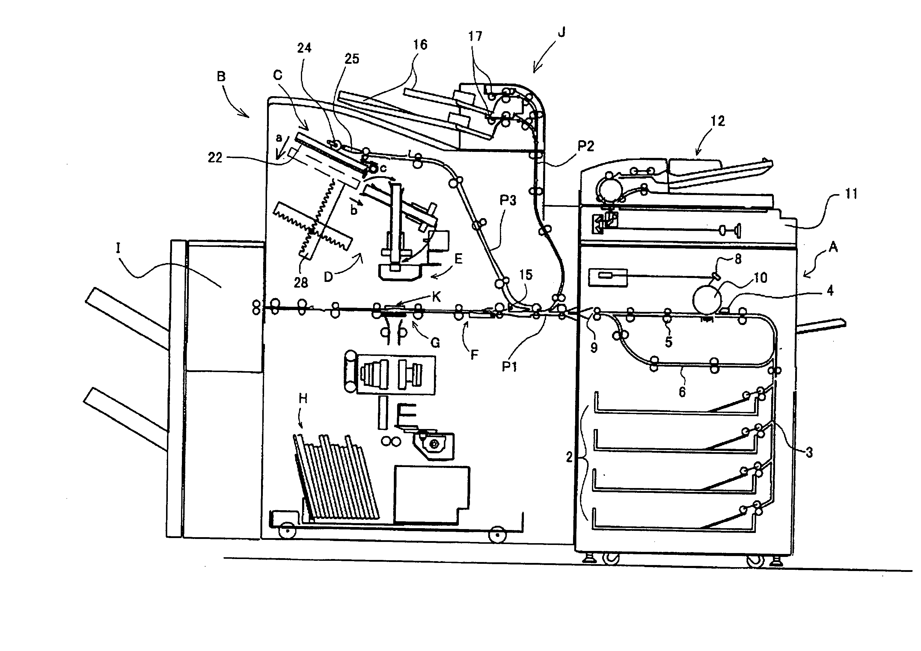
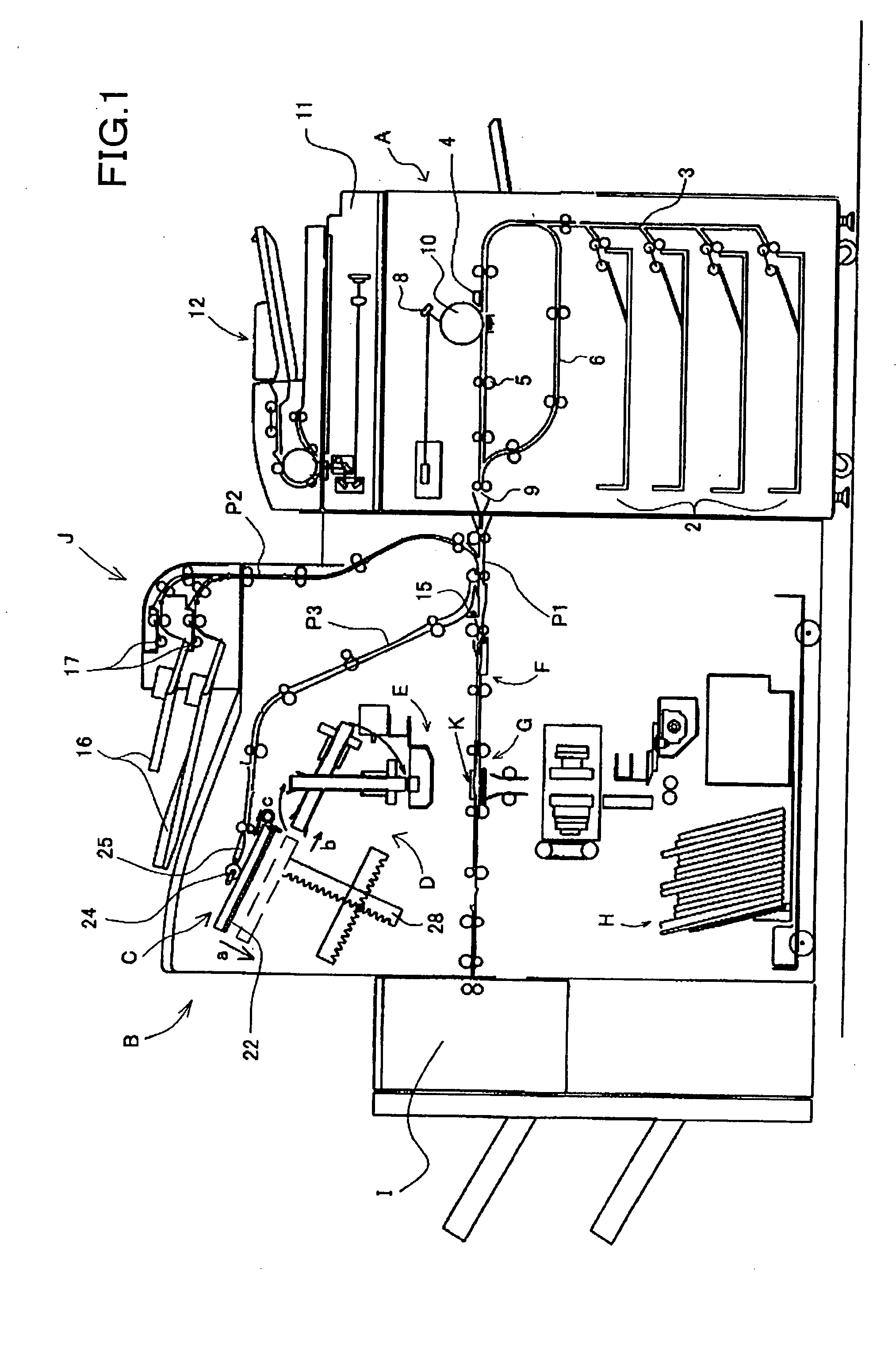
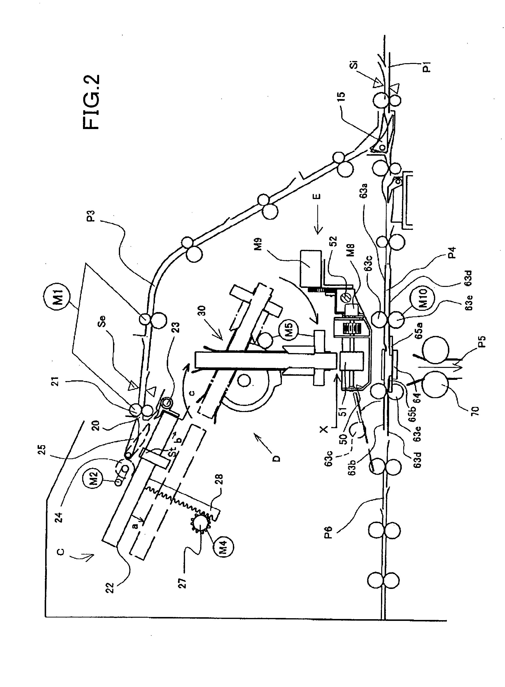
[0033] With reference to the drawings, a detailed description will be given below of an embodiment of a sheet feeding device and an image reading device in accordance with the present invention. FIG. 1 is a diagram showing the entire configuration of a bookbinding device in accordance with the present invention. FIG. 2 is an enlarged diagram illustrating the essential part of the bookbinding device

[0034] A bookbinding device B in accordance with the present invention is coupled to an image forming apparatus A, for example, as shown in FIG. 1. The bookbinding device B arranges sheets with images formed thereon by the image forming apparatus A, into a bundle, applies an adhesive such as paste to end surfaces of the sheet bundle, joins the sheet bundle to a cover sheet, and back-folds and presses the cover sheet for bookbinding. The cover sheet is fed from a direction crossing a conveying path for the sheet bundle by the image forming apparatus or an inserter. FIG. 1 shows such an ima...


PUM


Abstract

A bookbinding device includes a collecting device for collecting sheets into a bundle and a bookbinding path that includes a sheet bundle conveying device, an adhesive applying device, a cover binding device, and a cover sheet feeding path. The cover binding device includes a back folding press member for the cover sheet and a back rest plate member to back up the cover sheet. A control device allows the back folding press member to execute a back folding process with a small gap formed between the back rest plate member and a back of the sheet bundle. The control device further allows the back of the sheet bundle to abut against the back rest plate member to forcibly cool the adhesive. The control device varies the time required for the cooling depending on the thickness of the sheet bundle.

Description

BACKGROUND OF THE INVENTION AND RELATED ART STATEMENT [0001] The present invention relates to a bookbinding device that sets sheets with images formed by an image forming apparatus or the like, applies an adhesive to the back of the sheet bundle, and binds a cover sheet to the sheet bundle. More specifically, the present invention relates to a bookbinding device that joins a sheet bundle with an adhesive applied to its back to the center of a front cover sheet, which is then back-folded for casing-in. [0002] Common bookbinding devices of this kind include automatic bookbinding devices serving as terminal devices for image forming apparatuses such as printers and printing machines to stack sheets with images formed thereon so as to arrange the sheets in a bundle, apply an adhesive to end surfaces of the sheet bundle, and bind the sheet bundle to a cover sheet. Other devices of this kind include bookbinding devices that set printed sheets fed from a sheet feeding port and then bind th...

Claims


Application Information

Patent Timeline
IPC IPC(8): B42C19/08
CPCB42C11/02G03G2215/00936G03G15/6544B42C13/006
Inventor SASAMOTO, SHINYAKITTA, KOUICHI
Owner NISCA KK
Why Eureka
Try Eureka