Method of fixing curved circuit board and wire bonding apparatus

a technology of wire bonding and circuit board, which is applied in the direction of printed circuit manufacture, non-electric welding apparatus, manufacturing tools, etc., can solve the problems of large and complex apparatus, inability to perform wire bonding, and inability to use bonding equipmen

Inactive Publication Date: 2007-12-13
SHINKAWA CO LTD
View PDF0 Cites 6 Cited by
  • Summary
  • Abstract
  • Description
  • Claims
  • Application Information

AI Technical Summary

Benefits of technology

[0010]In view of the above noted problems, an object of the present invention is to provide a simple method and bonding apparatus capable of straightening a curved circuit board and suction-hold the circuit board in a flat fashion on a suction stage in an efficient manner.

Problems solved by technology

However, a thinned circuit board often involves a curvature or warpage, resulting in a case in which the wire bonding cannot be performed because it is not possible to suction and fix such a circuit board to a suction stage by vacuum.
Therefore, such an arrangement cannot be provided with a heating arrangement at the lower portion of the suction stage, and consequently cannot be used for a bonding apparatus that performs bonding and heating at the same time.
However, in the conventional art shown in FIG. 6, there is a problem that a wire 12 connects the semiconductor die 14 and the circuit board 15 is bend by a wind pressure when air is blown from the upper face, and consequently that the wire 12 and the wire 12 are brought into contact with each other.
Further, in the conventional art shown in FIGS. 7(a) through 7(c), there is a problem that the apparatus becomes large and complex because it is necessary to provide a large driving arrangement besides the suction stage 23 even though a gripper driving arrangement is not necessary at a lower portion of the suction stage 23.

Method used


Image

  • Method of fixing curved circuit board and wire bonding apparatus
  • Method of fixing curved circuit board and wire bonding apparatus
  • Method of fixing curved circuit board and wire bonding apparatus

Examples


Embodiment Construction

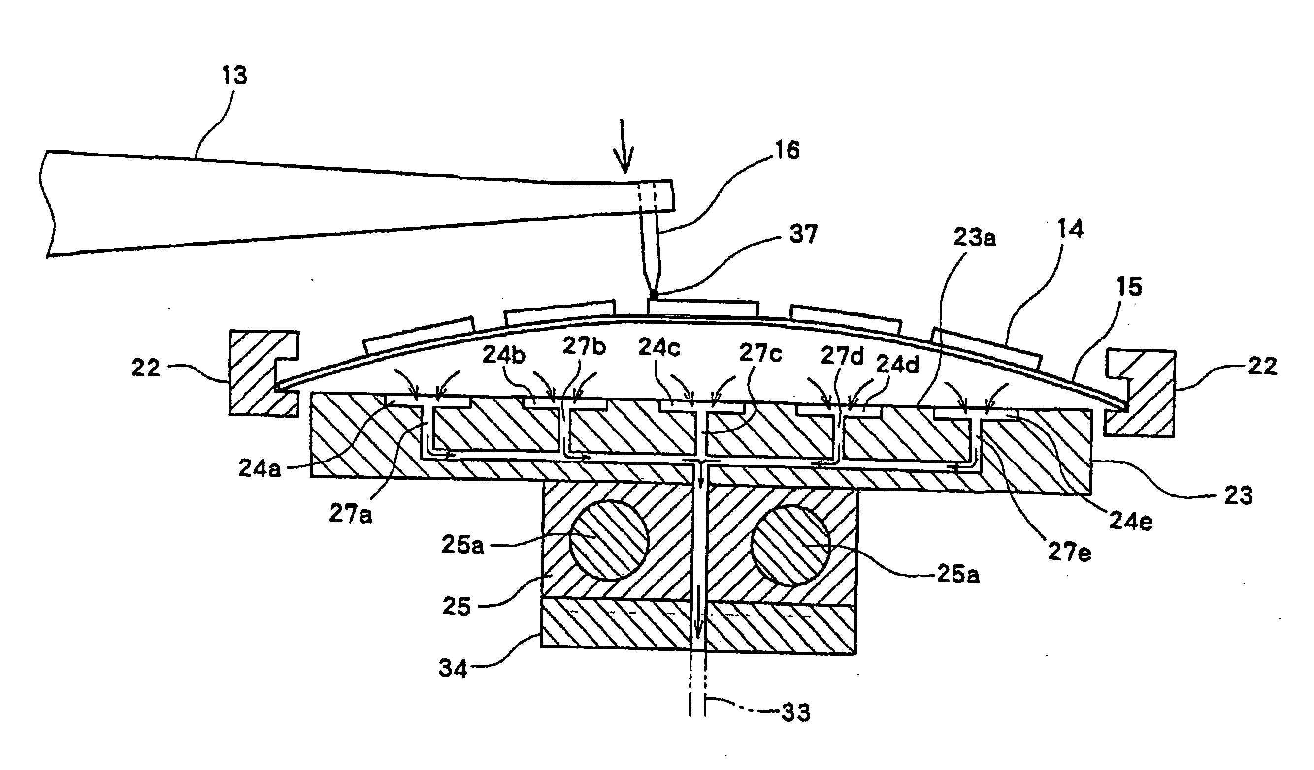
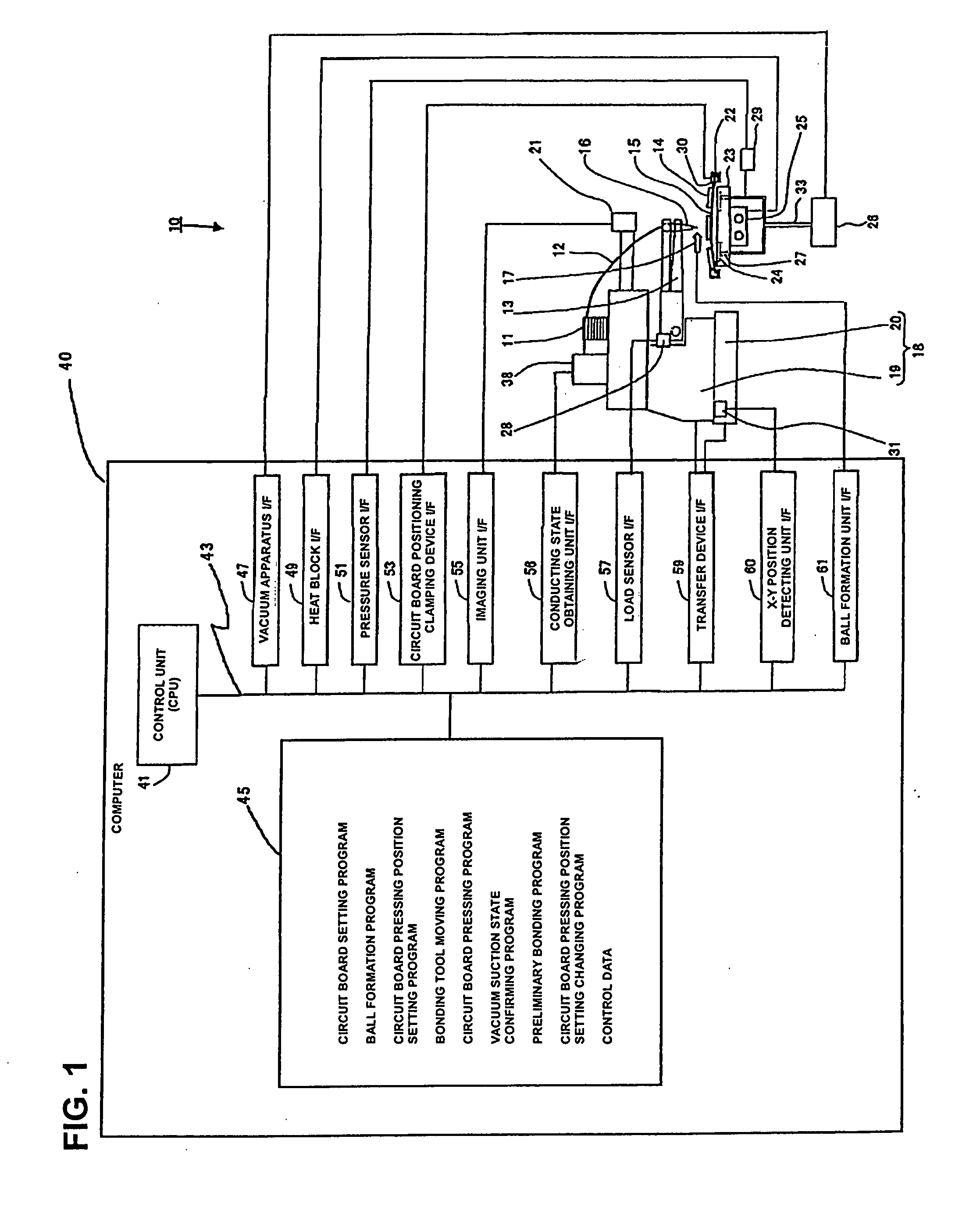
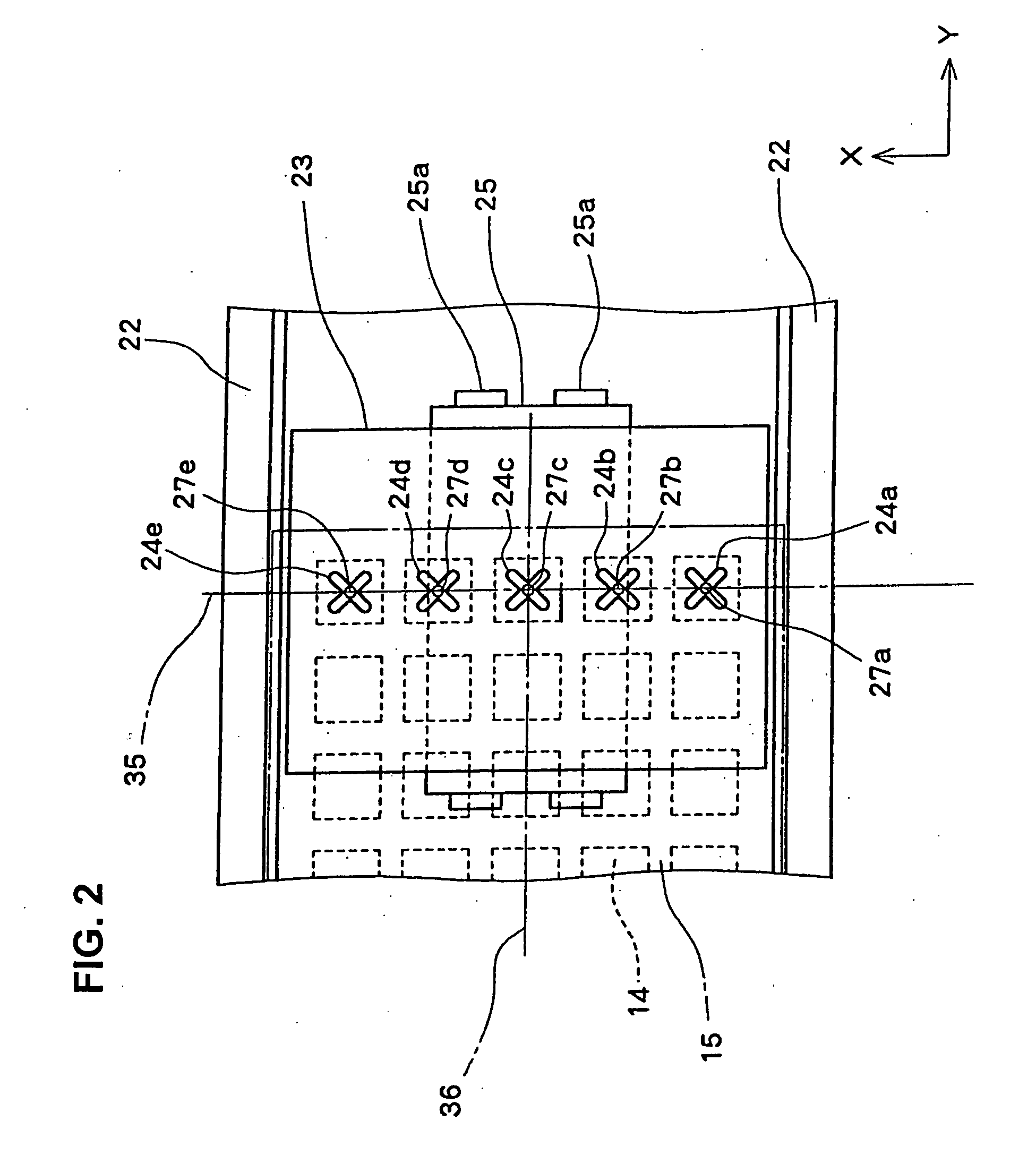
[0031]Hereinafter, preferred embodiments of the present invention will be concretely described with reference to the accompanying drawings. FIG. 1 is a diagram showing a system structure of a wire bonder to which a method of fixing a curved circuit board and a program therefor according to the embodiment of the present invention are applied. FIG. 2 is a top plan view showing the upper face of a suction stage of the wire bonder. FIG. 3 is a cross-sectional view of the suction stage of the wire bonder taken along the centerline 35 in an X-direction shown in FIG. 2.

[0032]As shown in FIG. 1, a wire bonder 10 is structured such that a bonding head 19 is disposed on an X-Y table 20, and the bonding head 19 is provided with a bonding arm 13 whose tip end is driven by a motor in a Z direction that is an up-down direction. A capillary 16 which is a bonding tool is attached to the bonding arm 13. The X-Y table 20 and the bonding head 19 structures a transfer device 18, which is able to move t...


PUM

PropertyMeasurementUnit
angleaaaaaaaaaa
diameteraaaaaaaaaa
timeaaaaaaaaaa

Abstract

A method of holding a curved circuit board in a flat fashion and a wire bonding apparatus thereof, including suction cavities provided in a suction stage to which a curved circuit board is suctioned. While evacuating air from the vacuum suction cavities, a capillary attached to the tip end of a bonding arm is lowered to press a part of the curved circuit board down thus having at least one of the vacuum suction cavities sealed by the circuit board, allowing the remaining vacuum suction cavities to be sealed successively so that the curved circuit board is straightened to be flat and suction-held on the suction stage. The vacuum suction cavities are sealed with by straightened circuit board, and the circuit board is held on the suction stage in place.

Description

BACKGROUND OF THE INVENTION[0001]The present invention relates to a method of suctioning a circuit board in place on a suction stage of a wire bonding apparatus and to a wire bonding apparatus executing the method.[0002]A typical wire bonder that connects a circuit board and a semiconductor die mounted on the circuit board by a wire performs wire-bonding while suctioning a lead frame being transferred by vacuum and fixing the lead frame to the upper face of a suction stage. On the other hand, with recent demands for thinned semiconductor packages with improved functionalities and manufacturing efficiency, circuit boards are increasingly thinned and large-sized and multi-layer mounting of dies or so-called stacking is more and more commonly employed. However, a thinned circuit board often involves a curvature or warpage, resulting in a case in which the wire bonding cannot be performed because it is not possible to suction and fix such a circuit board to a suction stage by vacuum.[00...

Claims


Application Information

Patent Timeline
Patent Type & Authority Applications(United States)
IPC IPC(8): H01L21/16
CPCB23K20/004Y10T29/49146H01L21/6838H01L24/78H01L24/85H01L2224/48091H01L2224/48225H01L2224/48465H01L2224/78301H01L2224/786H01L2224/78743H01L2224/851H01L2924/01047H01L2924/01082H01L2924/3511B23K20/005H01L2224/45139H01L2924/01033H01L2924/01006H01L2924/01005H01L2924/00014H01L2924/00H01L24/48H01L2224/45015H01L2224/48227H01L2224/78703H01L2924/00011H01L2224/45099H01L2924/01049H01L2924/207H01L21/02
Inventor NATSUME, RYUICHI
Owner SHINKAWA CO LTD
Why Eureka
Try Eureka