
Forward error correction decoding method and apparatus for satellite digital audio radio broadcasting

a technology of error correction and decoding method, applied in the direction of coding, code conversion, electrical equipment, etc., can solve the problems of significant degraded performance of current sdars receivers, difficult to achieve an approach, and often limited transmission system power and spectrum availability, so as to improve the overall performance of the decoder, improve the confidence of any corrected symbols, and improve the effect of error correction performan

Inactive Publication Date: 2007-12-13
AVAGO TECH INT SALES PTE LTD
View PDF5 Cites 10 Cited by
  • Summary
  • Abstract
  • Description
  • Claims
  • Application Information

AI Technical Summary

Benefits of technology

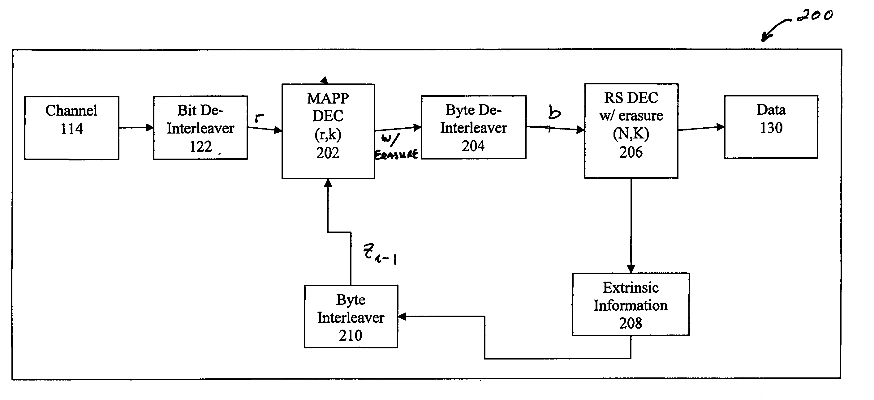
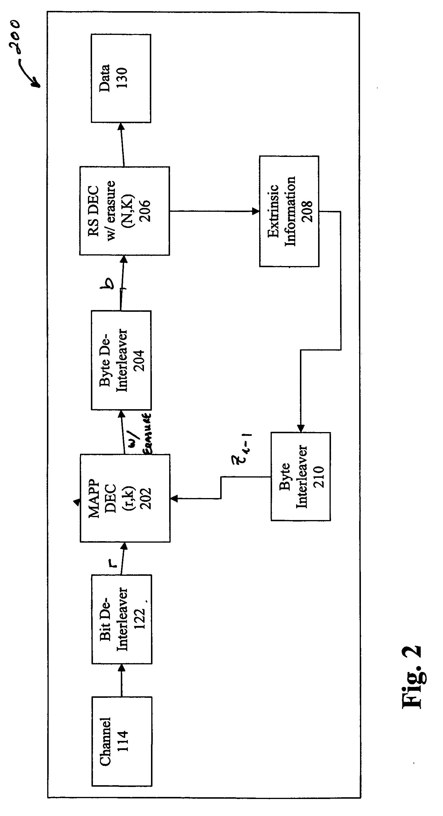
[0013]The present invention relates to an improved decoding scheme for use in a concatenated channel decoder. The decoder of the present invention utilizes a Maximal a posteriori (MAP) algorithm in place of the Viterbi algorithm used in the prior art. Further, in the present invention, the decoding of the concatenated code is done iteratively to increase the confidence for any corrected symbols. As a result, the overall performance of the decoder is improved. This iterative process comprises the MAP decoder generating hard decision information with three values: 1 and 0 for hard bit decision, and an Erasure flag if the MAP decoder is not confident about whether this decoded data bit is ‘1’ or ‘0’. The RS decoder, using this Erasure Information, attains better error correction performance than without having this Erasure Information. This improved output of the RS decoder combined with an RS decoder Error flag, which indicates whether the RS decoder output is correctable or not, are then supplied back to the MAP decoder as the new a priori information, thereby improving the performance of the system.

Problems solved by technology

Communication systems are often limited in terms of transmitter power and spectrum availability.
The performance of current SDARS receivers is degraded significantly in areas of dense foliage where the signal is weak.
This approach is not always possible and where it can be employed, it entails significant costs.
Not all of such serially concatenated codes are iteratively decoded in practice, however.
However, in practice, this serial concatenated code is not iteratively decoded.
However, although each decoder may be optimal for its specific task, the overall composite system may not be optimal for a given concatenated code.
One problem in such decoding processes is determining how the Viterbi algorithm is to be modified to accommodate inputs from Reed-Solomon decoded blocks that are correct.

Method used


Image

  • Forward error correction decoding method and apparatus for satellite digital audio radio broadcasting
  • Forward error correction decoding method and apparatus for satellite digital audio radio broadcasting
  • Forward error correction decoding method and apparatus for satellite digital audio radio broadcasting

Examples


Embodiment Construction

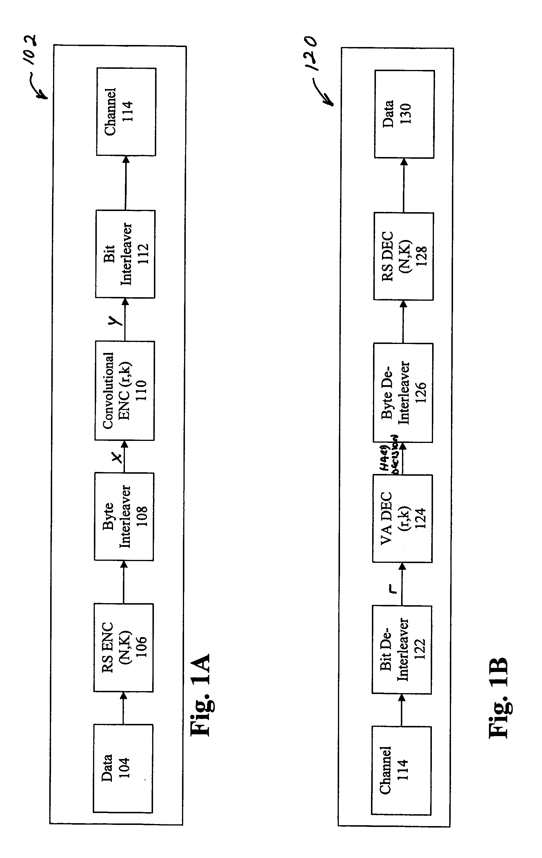
[0019]FIG. 2 illustrates an exemplary communications system decoder according to one embodiment of the invention. One distinguishing feature of the depicted decoder 200 over the prior art illustrated in FIG. 1B is the use of a maximal a posteriori (MAP) decoder 202 to generate hard decision bits plus Erasure indicators. The output of this decoder allows the decoding process to provide Erasure information rather than requiring the hard decisions outputted from the prior art VA decoder 124 of FIG. 1B. That is, based on the reliability of the MAP decoder, the output is quantized to one of three values: {1, 0, E} where {1, 0} are hard decision values derived when the reliability is larger than some threshold, and “E” (erasure) which is generated when the reliability is less than the threshold. The ‘E’ can be represented by a two bit value such as ‘11’.

[0020]The sequence of reliability values generated by the MAP decoder 202 is supplied to byte de-interleaver 204. Since the MAP decoder g...


PUM


Abstract

The present invention relates to an improved decoding scheme for use in a concatenated channel decoder. In the present invention, the decoding of the concatenated code is done iteratively to increase the confidence for any corrected symbols. As a result, the overall performance of the decoder is improved. This iterative process comprises using a Maximal a posteriori (MAP) decoder which generates decoded information, to include Erasure Information. The output of the MAP decoder is then supplied to a Reed Solomon (RS) decoder, which attains better error correction performance by using this Erasure Information. This improved output of the RS decoder is then supplied back to the MAP decoder, thereby improving the performance of the system.

Description

FIELD OF THE INVENTION[0001]The present invention relates generally to communication systems and iterative decoding performance. In particular, it relates to an improved method and apparatus for decoding data that has been encoded using a concatenated code consisting of a convolutional code and a Reed-Solomon (RS) code.BACKGROUND OF THE INVENTION[0002]Communication systems are often limited in terms of transmitter power and spectrum availability. For these and other reasons, it is often a goal of digital communications design to maximize the transmission bit rate R and minimize the probability of bit error, or Bit Error Rate (BER), for a given system power S, and bandwidth B. One example of such communications design relates to Satellite Digital Audio Radio Systems (SDARS). The performance of current SDARS receivers is degraded significantly in areas of dense foliage where the signal is weak. Further, this performance varies rapidly when deployed in a vehicle which is in motion. Pas...

Claims


Application Information

Patent Timeline
Patent Type & Authority Applications(United States)
IPC IPC(8): H03M13/00
CPCH03M13/2948H03M13/2936
Inventor SONGMALKEMES, ROBERT CONRAD
Owner AVAGO TECH INT SALES PTE LTD
Learn More