Phase lock loop and digital control oscillator thereof

a phase lock and digital control technology, applied in the direction of pulse automatic control, electrical equipment, etc., can solve the problems of delay time, difficult to achieve by conventional technology, etc., and achieve high bit number and high accuracy. , the effect of quick respons

Inactive Publication Date: 2007-12-20
NOVATEK MICROELECTRONICS CORP
View PDF8 Cites 23 Cited by
  • Summary
  • Abstract
  • Description
  • Claims
  • Application Information

AI Technical Summary

Benefits of technology

[0006] Accordingly, the present invention is directed to provide a phase lock loop for fractional-N frequency synthesis, wherein high bit number, high accuracy, and quick response to the change of N can be accomplished.
[0014] According to the present invention, the output clock signal is feedback to a time-to-digital converter and a period counter to be corrected, thus, the phase lock loop can correct the frequency of the output clock signal repeatedly according to the difference between the detected phase error and the estimative phase error, and eventually can make the frequency of the output clock signal to be N times of the input clock frequency. Moreover, since the phase lock loop of the present invention has the function of immediately detecting and correcting the frequency of the output clock signal, the phase lock loop can quickly respond to the change of N.
[0015] The phase lock loop in the present invention can be all-digital, or the bi-directional counter and the digital control oscillator of the output unit can be replaced with a loop filter and a voltage control oscillator, so that the phase lock loop becomes a digital / analog combination. The all-digital phase lock loop for fractional-N frequency synthesis is not easily affected by process variation and has smaller surface area, while the phase lock loop with analog output unit can provide a broad and continuous frequency distribution, and features better low-jitter characteristics.
[0016] Moreover, the digital control oscillator provided by the present invention adopts a structure including a dithering accumulator and a delay module, thus, the effective bit number of the frequency control value is increased by the dithering accumulator before the frequency control value is provided to the delay module with high bit number. Accordingly, the present invention provides clock frequency multiplication with high accuracy and high bit number.

Problems solved by technology

With such frequency multiplication method, first, the obvious disadvantage is that the frequency error of the circuit cannot be corrected immediately; instead, it can only be corrected after certain period until the output frequency reaches a wobble mean value, which may cause delay time.
Thus, high bit number and high accuracy is difficult to be accomplished by the conventional technology, and it takes a long time to reach the desired output frequency.

Method used


Image

  • Phase lock loop and digital control oscillator thereof
  • Phase lock loop and digital control oscillator thereof
  • Phase lock loop and digital control oscillator thereof

Examples


Embodiment Construction

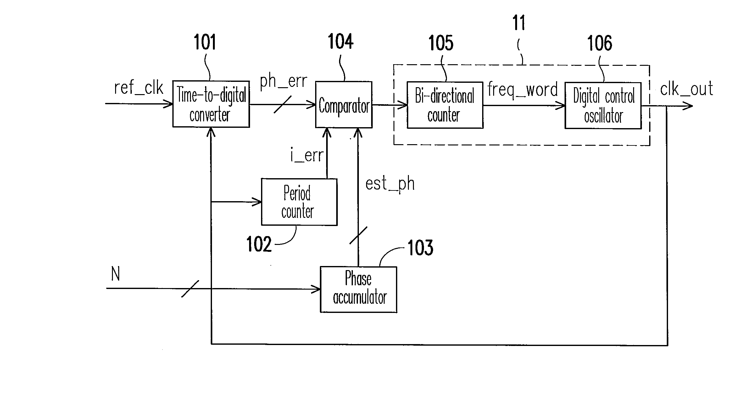
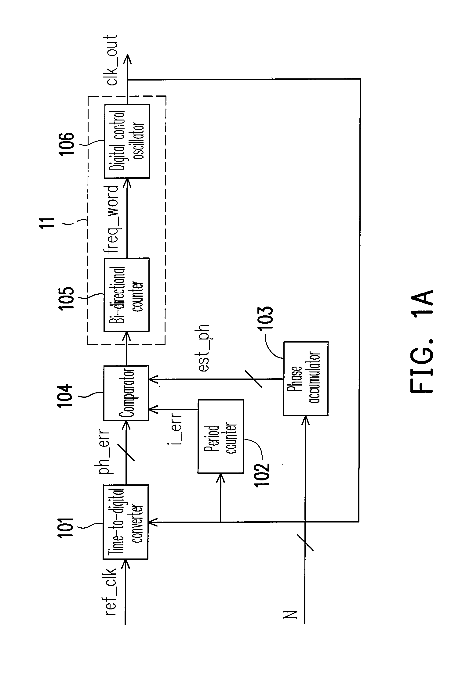
[0026]FIG. 1A is a circuit block diagram of a phase lock loop for fractional-N frequency synthesis according to an embodiment of the present invention. The phase lock loop includes a time-to-digital converter 101, a period counter 102, a phase accumulator 103, a comparator 104, and an output unit 11. Wherein the time-to-digital converter 101 outputs a detected phase error ph_err according to the timing difference between the reference clock signal ref_clk and the output clock signal clk_out. The period counter 102 stores and outputs a first accumulative value i_err and adds 1 to the first accumulative value i_err in each period of the output clock signal clk_out. The phase accumulator 103 adds N to a second accumulative value in each period of the reference clock signal ref_clk and outputs the estimative phase error est_ph according to the second accumulative value, wherein N is a real number greater than 0. In the present embodiment, the estimative phase error est_ph is the fractio...


PUM


Abstract

A phase lock loop including a time-to-digital converter, a period counter, a phase accumulator, a comparator, and an output unit is disclosed. The time-to-digital converter outputs a detected phase error based on the timing difference between a reference clock signal and an output clock signal. The period counter increases a first accumulative value in each period of the output clock signal. The phase accumulator increases a second accumulative value in each period of the reference clock signal and outputs the second accumulative value as an estimative phase error between the reference clock signal and the output clock signal in next period. The comparator outputs a frequency correction signal according to the detected phase error, the first accumulative value, and the estimative phase error. The output unit provides the output clock signal and adjusts its frequency according to the frequency correction signal.

Description

CROSS-REFERENCE TO RELATED APPLICATION [0001] This application claims the priority benefit of Taiwan application serial no. 95118388, filed May 24, 2006. All disclosure of the Taiwan application is incorporated herein by reference. BACKGROUND OF THE INVENTION [0002] 1. Field of the Invention [0003] The present invention relates to a phase lock loop. More particularly, the present invention relates to a phase lock loop for fractional-N frequency synthesis. [0004] 2. Description of Related Art [0005] Conventional phase lock loop for fractional-N frequency synthesis is used for receiving a reference-clock signal and providing an output clock signal whose frequency is N times as high as that of the reference clock signal, wherein N dose not have to be an integer. Instead, N can be any real number greater than 0. The frequency divider of such phase lock loop is usually controlled by sigma-delta modulator to obtain the required multiple. When generating non-integer frequency multiples, si...

Claims


Application Information

Patent Timeline
Patent Type & Authority Applications(United States)
IPC IPC(8): H03L7/00
CPCH03L7/091H03L7/1976H03L7/0997H03L7/093
Inventor HSIN, DON CHEN
Owner NOVATEK MICROELECTRONICS CORP
Why Eureka
Try Eureka