
Hard-coated antiglare film, and polarizing plate and image display including the same

a technology of polarizing plates and antiglare films, applied in the direction of polarising elements, identification means, instruments, etc., can solve the problems of deterioration of antiglare properties, glare occurrence, and insufficient solution of image sharpness and glare prevention in conventional hard-coated antiglare films, so as to prevent glare from occurring effectively, excellent antiglare properties and image sharpness, excellent display properties

Inactive Publication Date: 2007-12-20
NITTO DENKO CORP
View PDF8 Cites 39 Cited by
  • Summary
  • Abstract
  • Description
  • Claims
  • Application Information

AI Technical Summary

Benefits of technology

[0011]Accordingly, an object of the present invention is to provide a hard-coated antiglare film that is excellent in antiglare properties and image sharpness and that prevents glare from occurring, as well as a polarizing plate and an image display including the same.
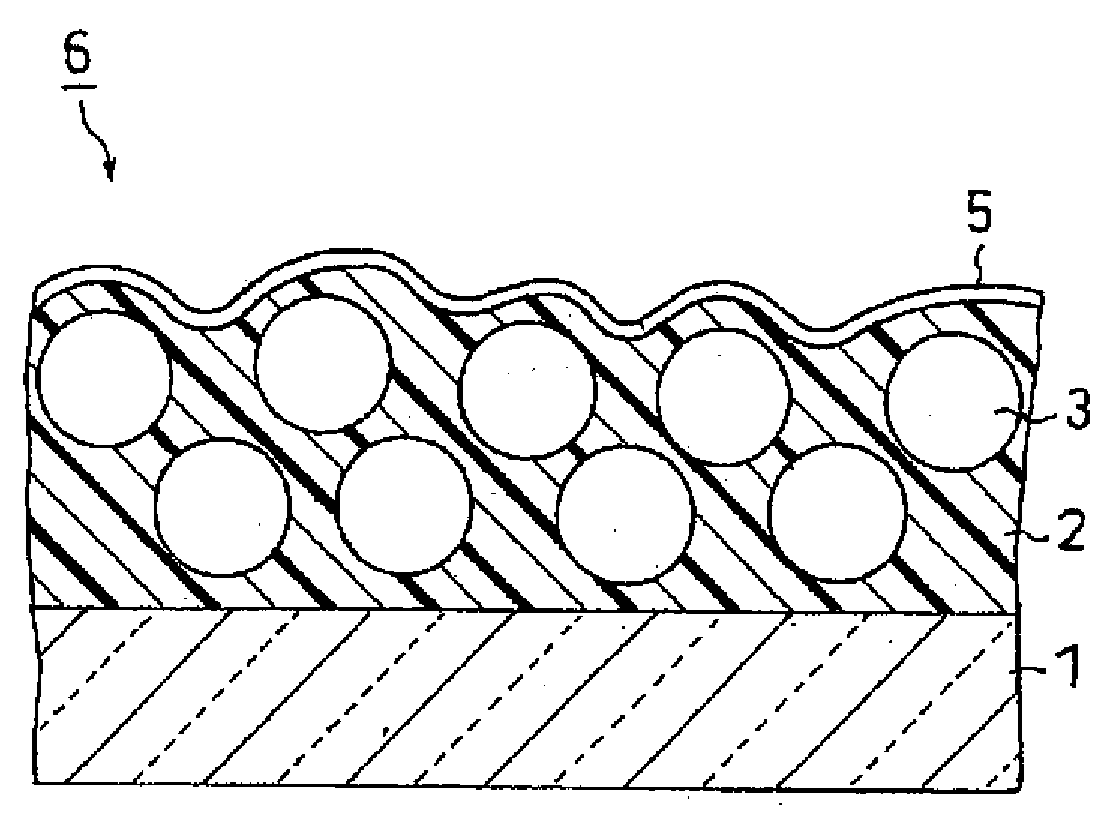
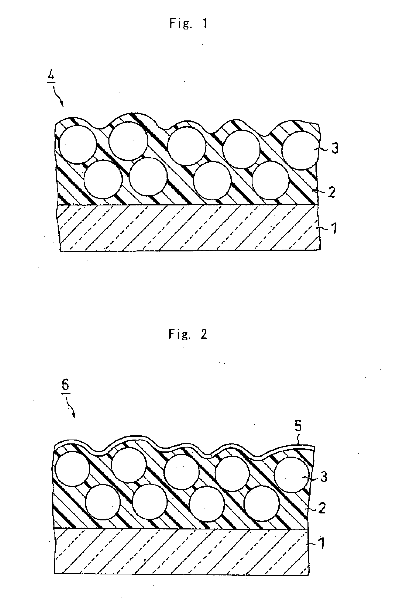
[0015]As described above, the hard-coated antiglare film of the present invention includes a hard-coating antiglare layer, and the three characteristics, i.e. the thickness of the hard-coating antiglare layer, the weight average particle size of the fine particles, and the difference in refractive index between the curable hard-coating resin that has been cured and the fine particles, are set in the respective predetermined ranges. The hard-coated antiglare film of the present invention may be excellent in both antiglare properties and image sharpness and can prevent glare from occurring effectively. Therefore an image display including a hard-coated antiglare film or polarizing plate of the present invention has excellent display properties.

Problems solved by technology

However, problems in both image sharpness and glare prevention have not been solved satisfactorily in these conventional hard-coated antiglare films.
Furthermore, decreased light scattering causes problems in deterioration in antiglare properties and occurrence of glare.

Method used


Image

  • Hard-coated antiglare film, and polarizing plate and image display including the same
  • Hard-coated antiglare film, and polarizing plate and image display including the same
  • Hard-coated antiglare film, and polarizing plate and image display including the same

Examples


example 1

[0099]A resin material (GRANDIC PC1097 (trade name), manufactured by DAINIPPON INK AND CHEMICALS, INCORPORATED, with a solid concentration of 66% by weight) was prepared. The resin material contained Component A, Component B, Component C, a photopolymerization initiator, and a mixed solvent described below. Then 10 parts by weight of PMMA particles (MX1000 (trade name), manufactured by SOKEN CHEMICAL & ENGINEERING CO., LTD., with a refractive index of 1.49) whose weight average particle size was 10 μm, and 0.1 part by weight of a leveling agent (GRANDIC PC-F479 (trade name), manufactured by DAINIPPON INK AND CHEMICALS, INCORPORATED) were added and mixed to 100 parts by weight of solid content of the resin material described above. This mixture was diluted with a solvent (ethyl acetate) in such a manner that a solid concentration of 55% by weight was obtained. Thus a material for forming a hard-coating antiglare layer was prepared. The material for forming a hard-coating antiglare la...

example 2

[0105]An intended hard-coated antiglare film was obtained in the same manner as in Example 1 except that the number of parts of fine particles to be added was changed to 30 parts by weight with respect to 100 parts by weight of solid content of resin raw material.

example 3

[0106]An intended hard-coated antiglare film was obtained in the same manner as in Example 1 except that the number of parts of fine particles to be added was changed to 50 parts by weight with respect to 100 parts by weight of solid content of resin raw material.


PUM

PropertyMeasurementUnit
Thicknessaaaaaaaaaa
Percent by massaaaaaaaaaa

Abstract

A hard-coated antiglare film is provided that is excellent in antiglare properties and image sharpness and that can prevent glare from occurring. The hard-coated antiglare film includes a transparent plastic film substrate and a hard-coating antiglare layer that is formed on at least one surface of the transparent plastic film substrate and that is formed of fine particles and a curable hard-coating resin. The hard-coating antiglare layer has a thickness in the range of 20 to 30 μm. The fine particles have a weight average particle size in the range of 7 to 15 μm. The difference obtained by subtracting the refractive index of the fine particles from that of the curable hard-coating resin that has been cured is in the range of −0.06 to −0.01 or 0.01 to 0.06.

Description

CROSS-REFERENCE TO RELATED APPLICATIONS[0001]This application claims priority from Japanese Patent Application No. 2006-166747, filed on Jun. 15, 2006. The entire subject matter of the Japanese Patent Application is incorporated herein by reference.FIELD OF THE INVENTION[0002]The present invention relates generally to hard-coated antiglare films, and polarizing plates and image displays including the same.BACKGROUND OF THE INVENTION[0003]With technical improvement in recent years, liquid crystal displays (LCDs), plasma display panels (PDPs), electroluminescence displays (ELDs), etc. have been developed in addition to conventional cathode ray tubes (CRTs) as image displays and have been used in practical applications. As LCDs have been technically improved to provide wide viewing angles, high resolution, high response, good color reproduction, and the like, applications of LCDs are spreading from laptop personal computers and monitors to television sets. In a basic LCD structure, a p...

Claims


Application Information

Patent Timeline
IPC IPC(8): G02B27/00G02B1/10B32B27/18C08J7/043C08J7/046G02B1/11G02B1/14G02B5/30G09F9/00
CPCG02B1/111C08J2475/04C08J2433/12C08J7/042C08J7/043C08J7/046G02B5/02G02F1/1335
Inventor HAMAMOTO, DAISUKETAKAO, HIROYUKIKIMURA, YUUICHITAKADA, KATSUNORIKUSUMOTO, SEIICHISHIGEMATSU, TAKAYUKI
Owner NITTO DENKO CORP
Learn More