Heat Transfer Systems for Dissipating Thermal Loads From a Computer Rack

a technology of heat transfer system and computer rack, which is applied in the direction of electrical apparatus, electrical apparatus contruction details, cooling/ventilation/heating modifications, etc., can solve the problems of generating a considerable amount of heat, consuming significant amounts of power, and operating these computer processors and memory modules requires a significant amount of power, so as to achieve the effect of dissipating thermal loads, dissipating thermal loads, and dissipating thermal loads

Inactive Publication Date: 2007-12-20
IBM CORP
View PDF10 Cites 83 Cited by
  • Summary
  • Abstract
  • Description
  • Claims
  • Application Information

AI Technical Summary

Problems solved by technology

Operating these computer processors and memory modules requires a significant amount of power.
Often processors can consume over 100 watts during operation.
Consuming significant amounts of power generates a considerable amount of heat.
Unless the heat is removed, the heat generated by a computer processor or memory module may degrade or destroy the component's functionality.
The drawback of traditional heat sinks is that such heat sinks typically require large amounts of physical space and increase the temperature of the environment surrounding the heat sink.
There is often not enough physical space inside the blade server chassis to install a traditional heat sink of adequate size to cool the processors or memory modules.
Even if the physical space does exist to install some heat sinks, the heat dissipated by the heat sinks typically raises the temperature in the computer room significantly.
Such an increase in the temperature in the environment surrounding the heat sinks reduces the heat sinks' ability to dissipate the thermal load.
Often a costly, second cooling solution is required to reduce the temperature in the computer room to an acceptable level.
The drawback to current liquid cooling technologies is that such technologies typically utilize a liquid cooler a few centimeters away from the electronic component that takes up as much physical space as a traditional heat sink—often because liquid cooler utilizes a traditional heat sink.
The drawback to such solutions is that these solutions are costly, cumbersome, and typically do nothing to reduce the heat released into the computer room.

Method used


Image

  • Heat Transfer Systems for Dissipating Thermal Loads From a Computer Rack
  • Heat Transfer Systems for Dissipating Thermal Loads From a Computer Rack
  • Heat Transfer Systems for Dissipating Thermal Loads From a Computer Rack

Examples


Embodiment Construction

Detailed Description

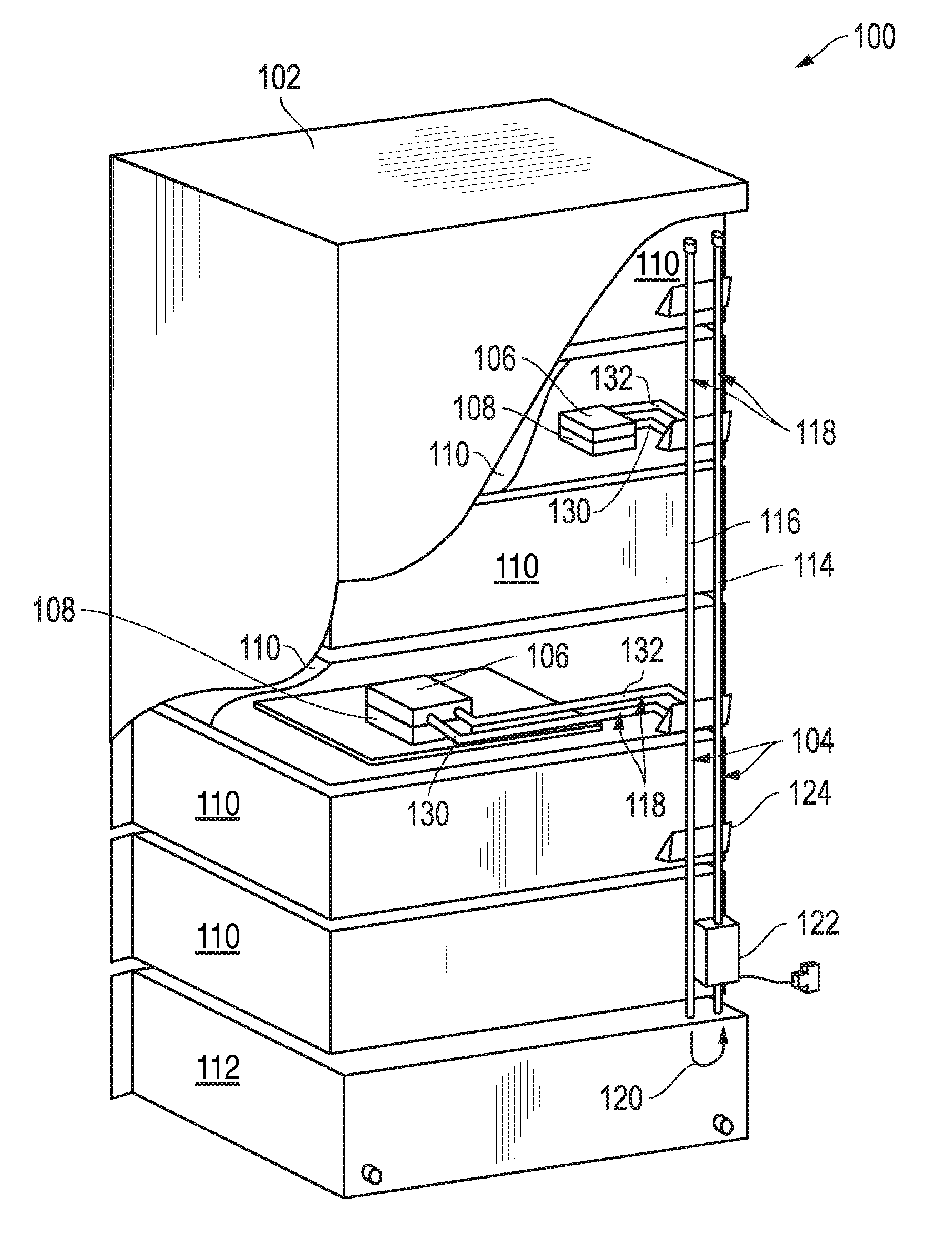
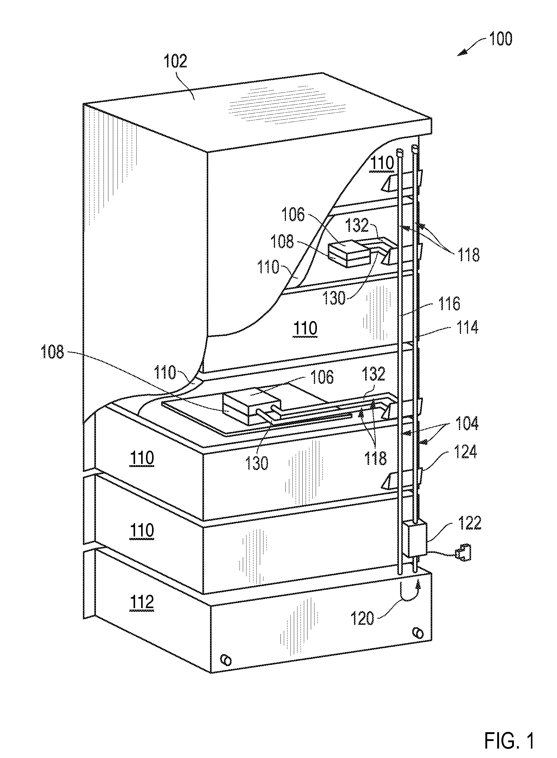
[0017]Exemplary heat transfer systems for dissipating thermal loads from a computer rack, expandable heat transfer buses for dissipating thermal loads from a computer rack, and methods for configuring the dissipation of thermal loads from heat sinks in a computer rack according to embodiments of the present invention are described with reference to the accompanying drawings, beginning with FIG. 1. FIG. 1 sets forth a perspective view of an exemplary heat transfer system (100) for dissipating thermal loads from a computer rack (102) according to embodiments of the present invention. A thermal load is the thermal energy generated by an electronic component (108) such as, for example, a computer processor or memory module. A measure of thermal load is typically expressed in units of Joules. The rate at which an electronic component (108) produces a thermal load over time is typically expressed in units of Watts.

[0018]The computer rack (102) illustrated in FIG. 1 is ...


PUM


Abstract

Heat transfer systems for dissipating thermal loads from a computer rack are disclosed that include: an expandable heat transfer bus extending along the rack, the expandable heat transfer bus capable of passing a thermal transport; one or more heat sinks connected to the expandable heat transfer bus, each heat sink capable of receiving the thermal transport from the bus and returning the thermal transport to the bus, and each heat sink capable of transferring into the thermal transport a thermal load from an electronic component inside a rack module mounted to the rack; and a heat exchanger connected to the expandable heat transfer bus capable of dissipating the thermal load of the thermal transport.

Description

BACKGROUND OF THE INVENTION[0001]1. Field of the Invention[0002]The field of the invention is heat transfer systems for dissipating thermal loads from a computer rack, expandable heat transfer buses for dissipating thermal loads from a computer rack, and methods for configuring the dissipation of thermal loads from heat sinks in a computer rack.[0003]2. Description of Related Art[0004]The development of the EDVAC computer system of 1948 is often cited as the beginning of the computer era. Since that time, users have relied on computer systems to simplify the process of information management. Today's computer systems are much more sophisticated than early systems such as the EDVAC. Such modem computer systems deliver powerful computing resources to provide a wide range of information management capabilities through the use of computer software such as database management systems, word processors, spreadsheets, client / server applications, web services, and so on.[0005]In order to del...

Claims


Application Information

Patent Timeline
Patent Type & Authority Applications(United States)
IPC IPC(8): H05K7/20
CPCH05K7/20781
Inventor GILLILAND, DON A.HUETTNER, CARY M.
Owner IBM CORP
Why Eureka
Try Eureka