Forward-looking sonar and underwater image display system

a display system and sonar technology, applied in the field of forward-looking sonar, can solve the problems of poor direction measurement accuracy, difficult to find obstacles, and the sonar apparatus requires considerable time for searching for obstacles, and achieves the effect of wide sounding area

Inactive Publication Date: 2007-12-20
FURUNO ELECTRIC CO LTD
View PDF3 Cites 41 Cited by
  • Summary
  • Abstract
  • Description
  • Claims
  • Application Information

AI Technical Summary

Benefits of technology

[0016] In light of the foregoing, it is an object of the invention to provide a forward-looking sonar which can search through a wide sounding area by using a transducer array formed by a relatively small number of elements without causing a problem of return echo dropout even when multiple echoes arrive at the same time.

Problems solved by technology

The aforementioned prior art arrangements however have their respective drawbacks.
Specifically, one drawback of the arrangement of U.S. Pat. No. 5,675,552 is that the sonar apparatus requires considerable time for searching for obstacles.
Since the transducer transmits acoustic waves and receives return echoes in one direction to another in a step-by-step sequence, it normally takes a good deal of time to obtain an underwater cross-sectional image within a 90-degree fan-shaped search area ahead of a vessel.
Another drawback of the arrangement of U.S. Pat. No. 5,675,552 is poor direction measuring accuracy.
This approach results in an increase in physical size and manufacturing cost of the transducer, also imposing a problem related to transducer installation.
The aforementioned arrangement of U.S. Pat. No. 5,530,680 has a drawback in that the echo sounding apparatus has a limited sounding range.
Sensitivity to return echoes is also low and the sounding range is limited since the return echoes are received by each of the two paired elements alone.
Another drawback of the arrangement of U.S. Pat. No. 5,530,680 is losses, or dropouts, of return echo data.
This causes a problem of echo data dropout.

Method used


Image

  • Forward-looking sonar and underwater image display system
  • Forward-looking sonar and underwater image display system
  • Forward-looking sonar and underwater image display system

Examples


first embodiment

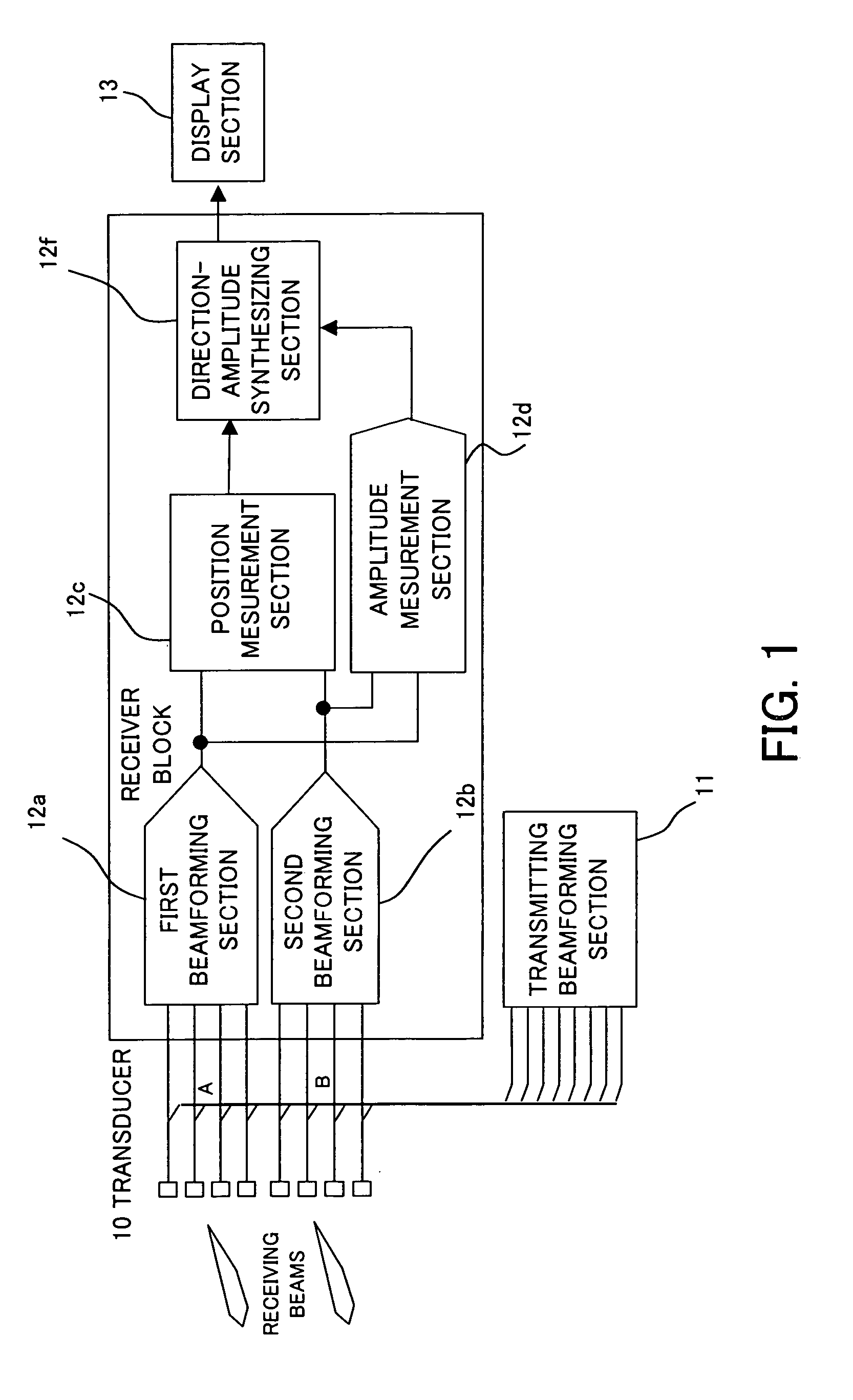
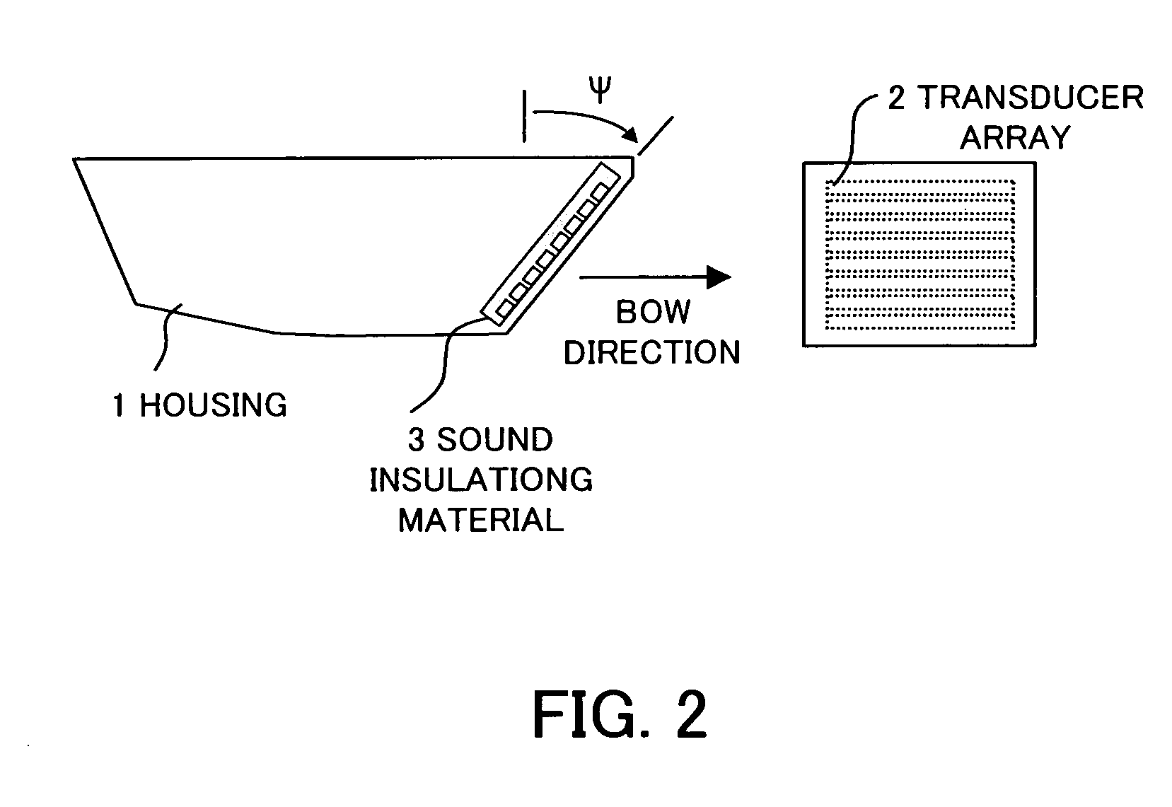
[0063]FIG. 1 is a block diagram of a forward-looking sonar according to a first embodiment of the invention, and FIG. 2 is a diagram generally showing the structure of a transducer 10 of the forward-looking sonar.

[0064] The transducer 10 includes a housing 1 and a transducer array 2 fixed to the housing 1. The transducer array 2 is made up of a plurality of transducer elements which are arranged in line, constituting a linear array. Generally, the transducer array 2 is installed at the bow of a vessel with a radiating surface (front surface) of the transducer 10 oriented in a forward direction of the vessel and inclined downward by a properly determined tilt angle Ψ (typically 30 degrees to 45 degrees) from a vertical direction as shown in FIG. 2. Side and rear surfaces of the individual transducer elements are covered by a sound insulating material 3, such as cork, whereas the front surface of the transducer 10, through which acoustic waves are radiated and received, is covered wi...

second embodiment

[0091]FIG. 10 is a block diagram of a forward-looking sonar according to a second embodiment of the invention. The forward-looking sonar of the second embodiment differs from that of the first embodiment (FIG. 1) in that the former additionally includes a synthesizer section 12e. In FIG. 10, elements identical or similar to those of the first embodiment are designated by the same reference numerals.

[0092] The synthesizer section 12e calculates the center of gravity of echo intensities of an echo detected by the main beam B3 as well as the variance of echo intensities along a range direction in each main beam direction. Then, the synthesizer section 12e determines the position of the echo (target) from the center of gravity within a range below a predefined variance value and synthesize the position thus obtained with the position of the echo (target) determined by the position measurement section 12c.

[0093] Although it is possible to decrease the number of echo signal dropouts by ...

third embodiment

[0110] A third embodiment of the invention is now described.

[0111] In this embodiment, the synthesizer section 12e calculates the center of gravity of echo intensities of an echo detected by the main beam B3 (refer to FIG. 3) along a beam steering direction at each distance. Then, the synthesizer section 12e determines the position of the echo (target) from the distance to the echo (target) and the center of gravity and synthesize the position thus obtained with the position of the echo (target) determined by the aforementioned position measurement means. FIGS. 19A and 19B are diagrams illustrating a method of determining the center of gravity of echo signal intensities along a beam steering direction.

[0112] Echo signals obtained from an amplitude display of FIG. 19A are arranged along the beam steering direction θ (FIG. 19B) and a maximal value of echo levels is determined. Echo signals of which amplitudes are equal to or larger than a specific amplitude value which is properly d...


PUM


Abstract

A forward-looking sonar includes a transducer array which is divided into a first sub array and a second sub array, a first beamforming section for forming a first receiving beam with the first sub array, and a second beamforming section for forming a second receiving beam with the second sub array. The forward-looking sonar receives target echoes from a wide sounding area with these receiving beams. The forward-looking sonar further includes a position measurement section for determining the position of a target based on the direction of the target calculated from a phase difference between the echoes from the target received by the first and second receiving beams by a split-beam method and the distance to the target calculated from time needed for receiving the echoes after transmission.

Description

BACKGROUND OF THE INVENTION [0001] 1. Field of the Invention [0002] The present invention relates to a forward-looking sonar for displaying echoes of objects ahead of a surface vessel by use of transmitted and reflected ultrasonic waves (hereinafter referred to as acoustic waves). More particularly, the invention pertains to a forward-looking sonar capable of measuring and visually presenting the distance and direction of any of such navigational hazards as shallows and underwater obstacles ahead of a surface vessel. [0003] 2. Description of the Related Art [0004] A forward-looking sonar for measuring and visually presenting the distance and direction of any of such navigational hazards as shallows, reefs, drifting surface objects, underwater obstacles and a sea bottom ahead of a surface vessel is installed as shown in FIG. 27. A transducer of the forward-looking sonar is typically installed on the hull of the vessel as illustrated. By using an acoustic sounding beam formed by the t...

Claims


Application Information

Patent Timeline
Patent Type & Authority Applications(United States)
IPC IPC(8): G01S15/89G01S7/52G01S15/42
CPCG01S7/52003G01S15/89G01S15/42
Inventor KAWABATA, YASUOHAMADA, TOKIHIKOKAIDA, HIDETOSHI
Owner FURUNO ELECTRIC CO LTD
Why Eureka
Try Eureka