Drill bit and dust collector attachment for drills

a technology for dust collectors and drills, which is applied in the field of drill bit attachments, can solve the problems of no known device providing this particular structure, dust and debris can easily spill out of this holding area, etc., and achieve the effects of convenient emptying and cleaning, avoiding the “mess” of furnishings, and avoiding the “mess” of dust collectors

Inactive Publication Date: 2007-12-20
CGP
View PDF24 Cites 21 Cited by
  • Summary
  • Abstract
  • Description
  • Claims
  • Application Information

AI Technical Summary

Benefits of technology

[0007] Advantage of the present invention over known devices is in the provision of a drill bit which is made of a shaft including a fan affixed thereon having at least one blade, and preferably up to six blades
[0008] Further advantage of the invention, is the inclusion of this drill bit within a drill attachment device for dust and debris collection which is cleaner and more efficient than known devices. In addition to the drill bit including a fan, the drill attachment includes a handle, a housing body, a nozzle and a receptacle to collect the dust and debris while the drill is in use.
[0009] The nozzle portion of the device has an opening at the tip and is lined with a rubber cushion (or similar material) which when placed on the drilling surface creates a tight fit on the surface. When the drill bit penetrates the drilling surface dust produced is driven by at least one fan blade back into a dust and debris receptacle on the handle. None of the known devices provides this particular structure.
[0010] The drill bit and drill attachment enables the user to drill any surface “dust-free”. The specific structure of the drill includes a rubber cushion or similar material at the tip of the attachment nozzle which when placed on the drilling surface creates a tight fit on the surface. When drilling begins the dust is collected in a dust and debris receptacle without dispersing within the room or area.
[0011] The invention is used to collect plaster, wood, brick, concrete, metal shavings and filings, dust and debris when drilling holes into these surfaces, thereby protecting the eyes, lungs and face while avoiding the “mess” of furnishings when performing repairs / alterations to offices, homes and the like.
[0012] Once drilling begins, dust and debris is propelled by the drill bit including a fan having at least one blade into the dust collection receptacle that is inside the handle portion of the device. The dust collection receptacle is preferably disposable and detaches for easy emptying and cleaning of the dust and debris.

Problems solved by technology

When the user removes the drill after use the dust and debris can very easily spill out from this holding area.
None of the known devices provides this particular structure.

Method used


Image

  • Drill bit and dust collector attachment for drills
  • Drill bit and dust collector attachment for drills
  • Drill bit and dust collector attachment for drills

Examples


Embodiment Construction

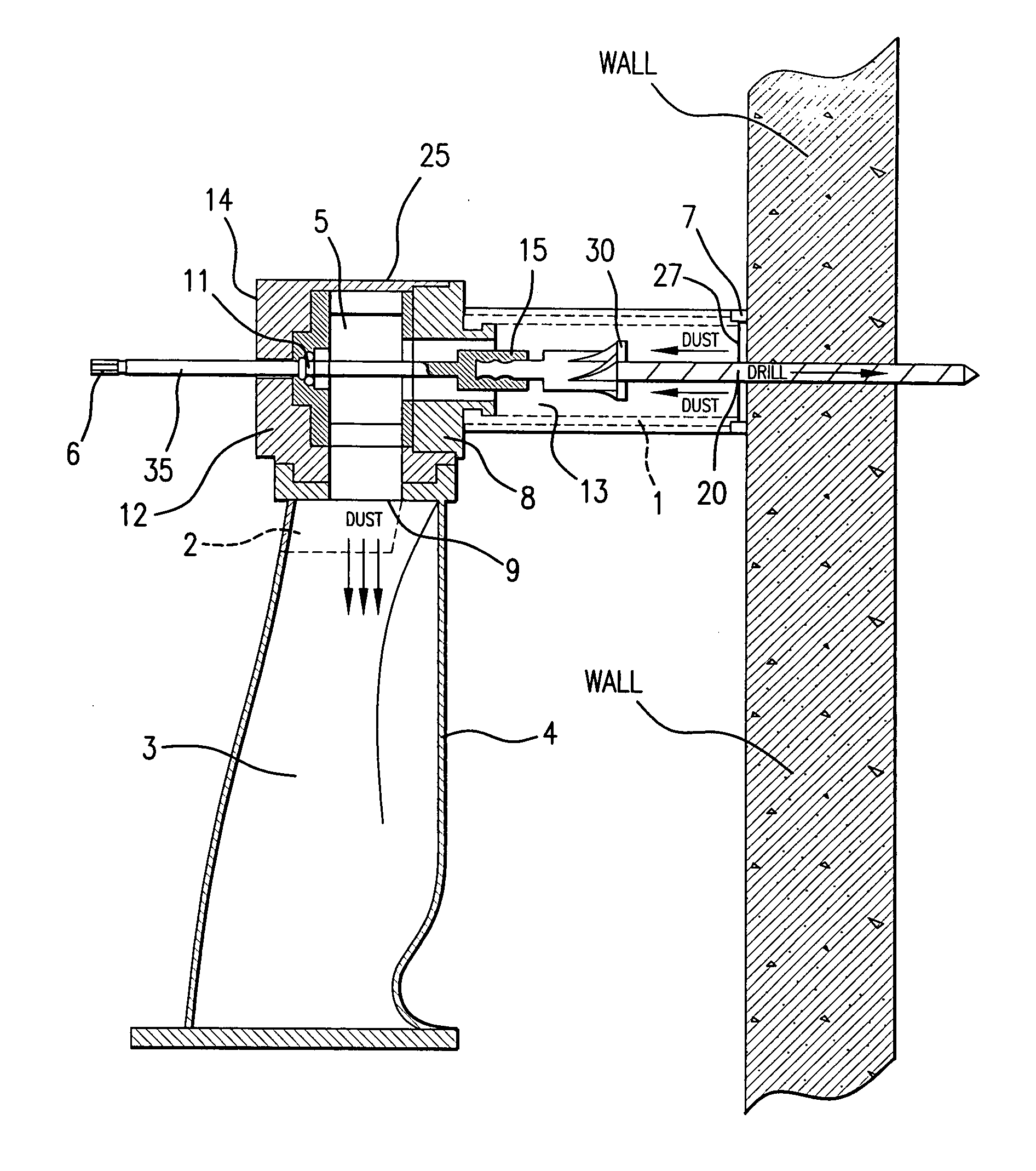
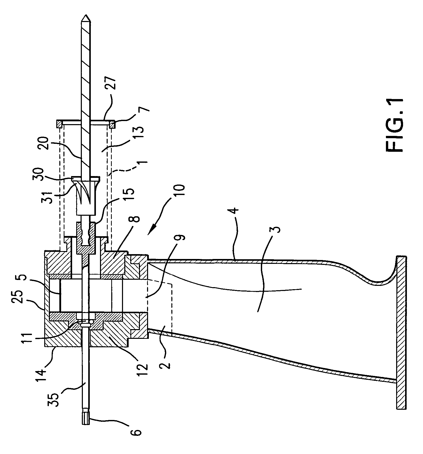
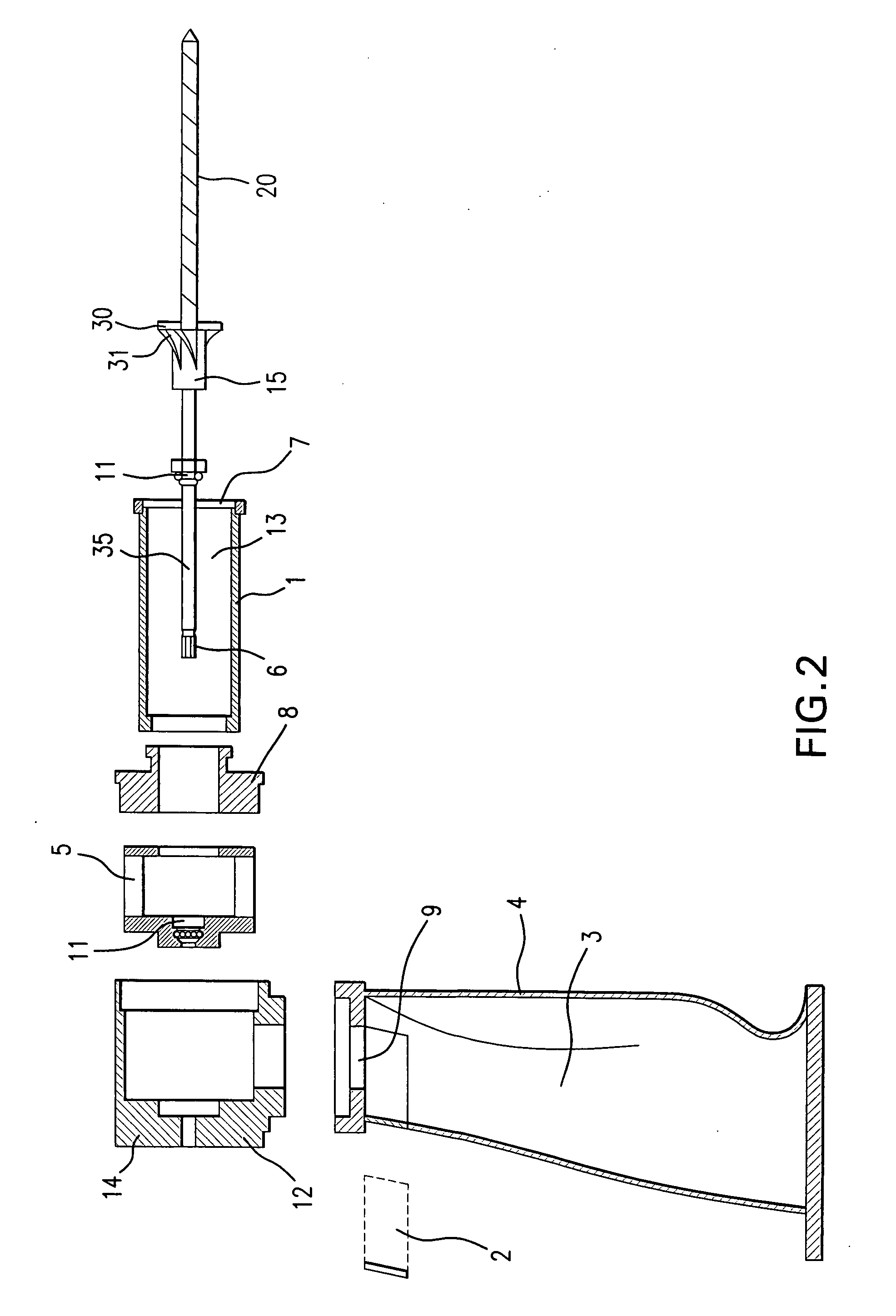
[0035] In accordance with the present invention a drill attachment for collecting dust and debris is provided. As described in the accompanying drawings the structures of the invention device are labeled as follows: [0036]1—Nozzle; [0037]2—Filter; [0038]3—Receptacle; [0039]4—Handle; [0040]5—Second Fan; [0041]6—Means for attachment to Drill Chuck; [0042]7—Nozzle Tip; [0043]8—Front portion Housing Body (attached to Nozzle); [0044]9—Opening from Housing Body into Receptacle; [0045]10—Drill Attachment Device; [0046]11—Locking Mechanism for Additional Shaft; [0047]12—Back portion Housing Body; [0048]13—Chamber within Nozzle; [0049]14—Back portion Housing Body attached to Drill; [0050]15—Chuck for Drill Bit; [0051]20—Drill Bit; [0052]25—Housing Body; [0053]27—Nozzle Aperture; [0054]30—Fan; [0055]31—Fan Blade; [0056]35—Additional Shaft; [0057]40—Spring loaded mechanism (in Nozzle); and [0058]51—Second Fan Blade.

[0059]FIG. 1 is a cross section of the drill attachment illustrating the gener...


PUM

PropertyMeasurementUnit
areaaaaaaaaaaa
structureaaaaaaaaaa
sizesaaaaaaaaaa

Abstract

A drill bit made of a shaft including a fan on the shaft having at least one blade; and related drill attachment for dust and debris collection made of a handle; a housing body having a front and back portion and a top and bottom portion, such that the bottom portion is connected to the handle and the housing body contains a hollow opening perpendicular to the handle; a nozzle which is connected to the front portion of the housing body; a drill bit comprising a shaft including a fan on the shaft having at least one blade within said hollow circular opening; and a receptacle to collect dust and debris while the drill is in use.

Description

[0001] This application claims the benefit of U.S. provisional application no. 60 / 809,012 filed May 26, 2006, which is incorporated herein in its entirety by reference.FIELD OF THE INVENTION [0002] The present invention relates to an attachment for drills, preferably electric drills, which collects dust and debris. More specifically, it relates to a drill bit including a fan blade to direct the dust particles to a receptacle for collection. BACKGROUND OF THE INVENTION [0003] The general disclosure of various tools which collect dust particles are known in the prior art. Representative patents include U.S. Pat. No. 6,851,900 B2 to Tillemans et al.; U.S. Pat. No. 6,557,261 B1 to Buser et al.; U.S. Pat. No. 6,379,091 B1 to Queipo; U.S. Pat. No. 6,095,724 to Hurt; U.S. Pat. No. 6,053,674 to Thompson; U.S. Pat. No. 5,980,446 to Loomis et al.; U.S. Pat. No. 5,497,841 to Cox et al.; U.S. Pat. No. 4,646,853 to Sugden et al.; U.S. Pat. No. 4,100,982 to Wilkinson et al.; and U.S. Pat. No. 3,9...

Claims


Application Information

Patent Timeline
Patent Type & Authority Applications(United States)
IPC IPC(8): B23B47/28B23Q11/00
CPCB23B51/12B23Q11/0046Y10T408/03Y10T408/50B23Q11/0071
Inventor COLON, JULIO A.
Owner CGP
Why Eureka
Try Eureka