Solar super structure with cooling system

a solar super structure and cooling system technology, applied in the direction of heat collector mounting/support, lighting and heating apparatus, light radiation electric generators, etc., can solve the problems of limiting the number of module plates installed on the return of nuclear powered electricity is considered but not welcomed in western society, and the solar cell module final size is too heavy for the roof of the ordinary house, etc., to achieve the maximum solar energy collection ability of the solar cell module, the effect of eliminating heat accumulation

Inactive Publication Date: 2007-12-27
OAK EUGENE
View PDF7 Cites 25 Cited by
  • Summary
  • Abstract
  • Description
  • Claims
  • Application Information

AI Technical Summary

Benefits of technology

[0010]The purpose of the current application is to provide a supporting frame structure to render maximum solar energy collecting ability of solar cell modules. These solar cell modules are installed on a house roof. The support frame structure is comprised of aluminum pipes, steel pipes, plastic plates, and woods. The frame structure has at least four vertical posts made of metal pipes, which support other metal pipes, constituting a planar frame for the upper horizontal frame. A patio with a sloped top, at least 2 meters high, is developed between the roof of the house and the bottom of the top surface of the frame throughout the whole roof. This space is used to install incidental facilities of the solar power systems such as pumps, batteries, and water tanks and to maintain those facilities. As a result, the side view of the rooftop frame structure, on which the solar cell panels are mounted, forms a rectangular triangle on a square. The angle between the sloped surface and the horizontal base is 3 to 75 degrees, depending on the latitude of the geometric location of the place on which the solar cell plate modules are installed. Maintenance accesses, developed between the solar cell module mounts, enable frequent cleaning and maintenance of the solar cell modules. Pluralities of cooling frames are installed between the solar cell panels and solar cell plate mounts to eliminate heat accumulated in the solar cell module plates and maintains temperature of the solar cells therein under 80° C. The cooling frame is comprised of 5 cm by 10 cm square wood frame with pass ways for air and mist of water. Latent heat of evaporating water takes out heat from the space within the cooling frame and keeps the solar cell panels cool. Side effect of the cooling frame is keeping the house under the structure cool.

Problems solved by technology

Solar cells have become highly recognized as a clean energy source for individual houses because of the high price of electricity generated by fossil fuels and excessive generation of carbon dioxide.
Returning of the nuclear powered electricity is considered but not welcomed in western society because of the safety issue of the power plant.
However, these methods teach only how to assemble each solar cell and the parts to connect them in a planar shape.
The final solar cell module for a house may be too heavy for a roof of an ordinary house.
Weight of those modules along with its ancillaries could limit the number of module plates installed on a roof.
In addition, it is not easy to clean the surface of the solar module plates.
Accordingly, the efficiency of generation of electricity is decreased due to the polluted air and dusts in big cities.
Flora, et al. illustrates in their U.S. Pat. No. 2,763,882 that silicon P—N junction material has higher rectifier efficiency at all temperatures up to about 220° C. But, a germanium rectifier, which is widely used for P—N—P junction composite for a solar cell, becomes quite inefficient at temperatures approaching 100° C. Consequently, rectifiers prepared from germanium must be cooled with great care in order to prevent the temperature from exceeding a certain predetermined maximum, which is ordinarily about 80° C. In a desert area, temperature usually reaches up to 65° C. in summer.
The cells are mounted within the enclosure on a resinous cushion that is relatively a good conductor of heat but a poor conductor of electricity.
Those solar cell modules are not the proper type for installing on the roof of private individual houses.

Method used


Image

  • Solar super structure with cooling system
  • Solar super structure with cooling system
  • Solar super structure with cooling system

Examples


Embodiment Construction

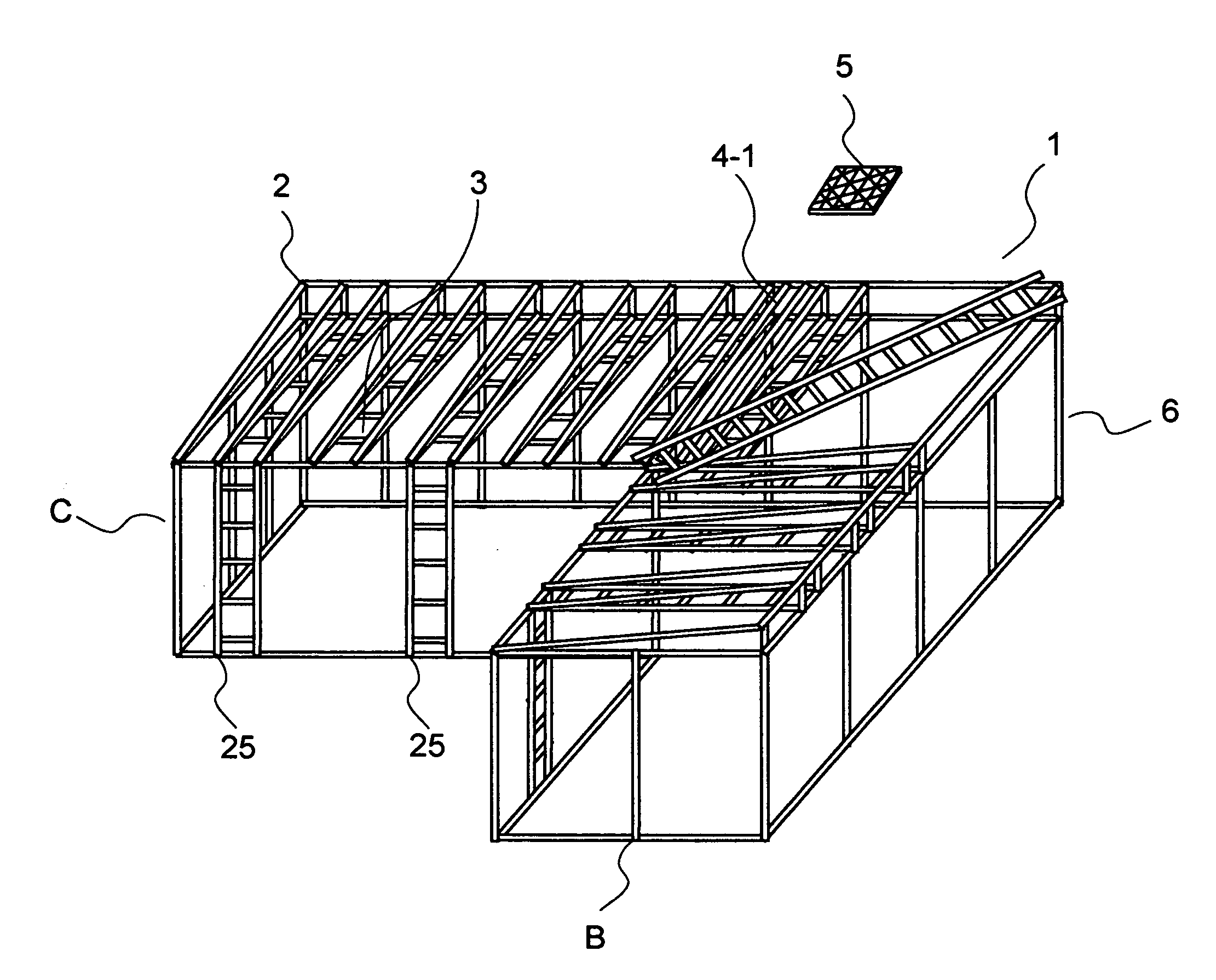
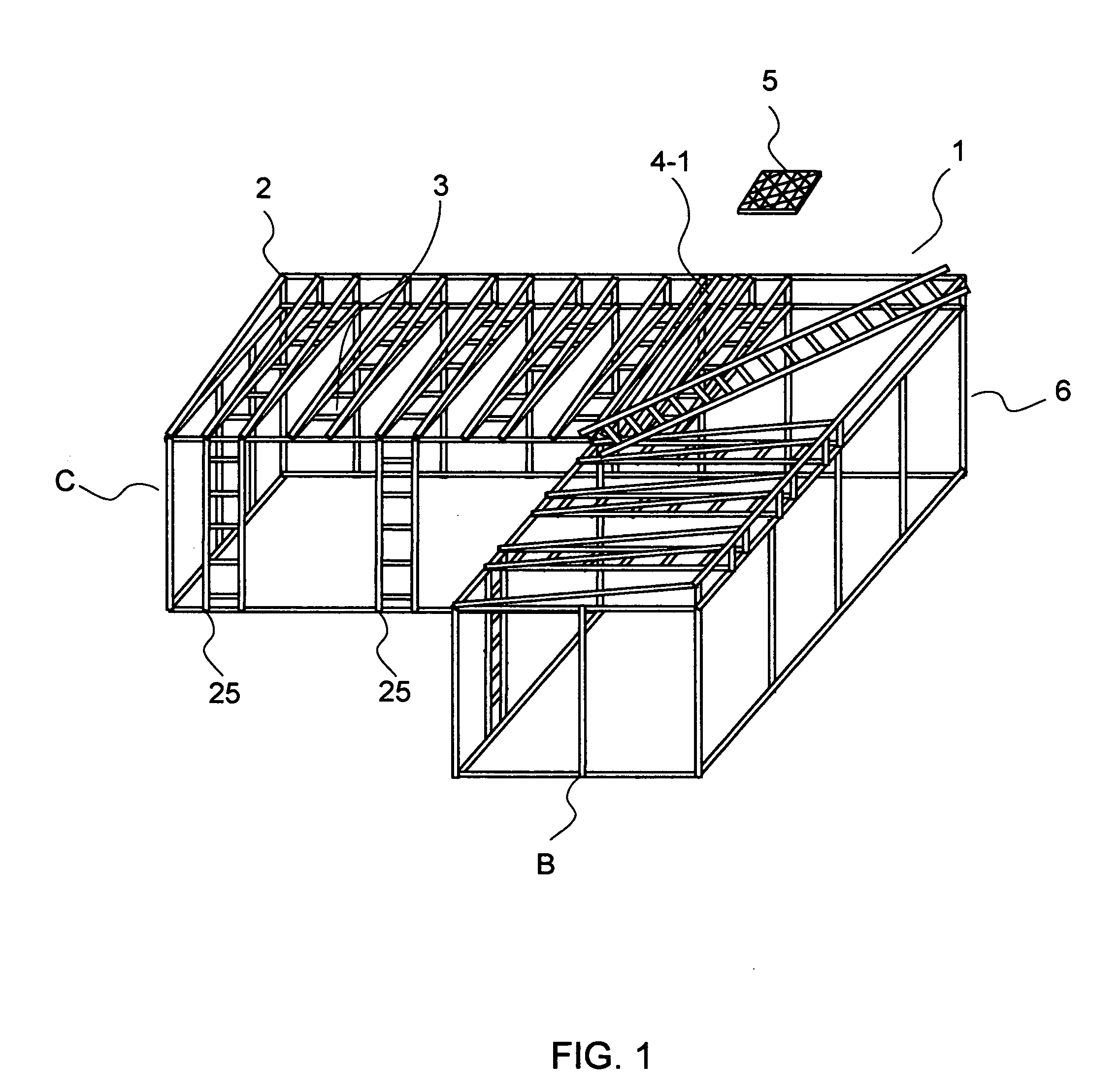
[0018]FIG. 1 is a perspective view of the solar cell module panel supporting frame structure (1) of the current application. The structure (1) is made of 5 cm by 5 cm square carbon steel pipes (2) welded to each other. Therefore, the structure (1) is self-sustaining. The upper face of the solar cell module panel supporting frame structure (1) is equipped with maintenance accesses (3) and solar cell module mounts (4). Solar cell module plates (5) of 180 cm by 76 cm are mounted on the mount (4) supported by cooling frame (4-1). The cooling frames (4-1) placed on a waterproof roofing (4-2) and bolted to the solar cell module mounts (4).

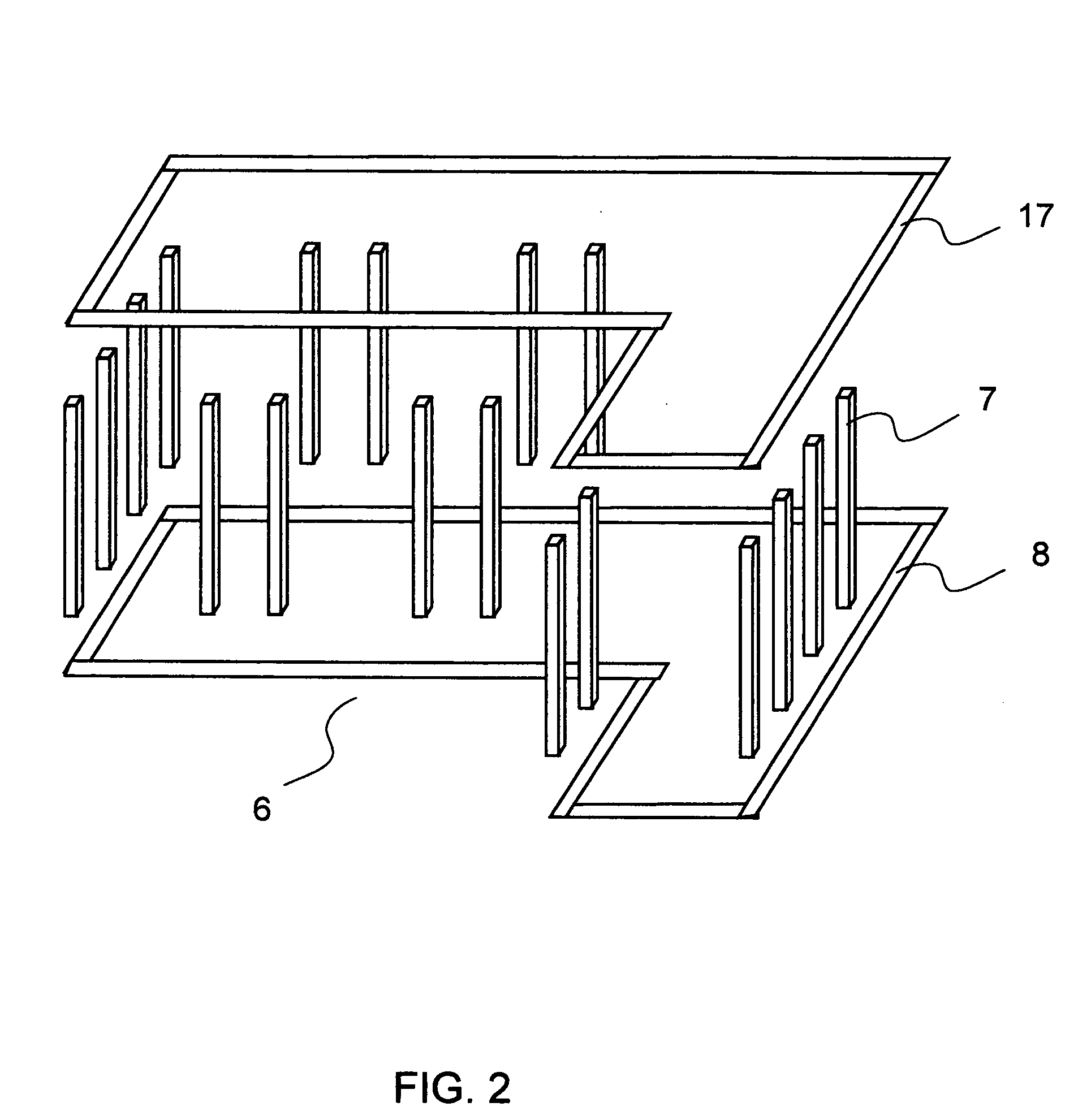
[0019]FIG. 2 is an exploded view of the lower part (6) of the solar cell module panel supporting frame structure (1). The lower part (6) of the structure (1) is in cubic form. Twenty 5 cm by 5 cm square carbon steel pipes (7) of 274 cm long are welded vertically on an “L” shape base (8) made with the same 5 cm by 5 cm square carbon steel pipes by cutting...


PUM


Abstract

Supporting frame structure for installing plain solar cell module plates and incidental facilities on a house roof is provided. The supporting structure is in the shape of pluralities of slope structured solar cell plate mount accompanied by cleaning accesses mounted on a rectangular cube frame. Side view of the solar cell plate mount forms a rectangular triangle on a square. The angle between the sloped top surface and the horizontal base is 3 to 75 degrees, depending on the latitude of the geometric location of the place where the solar cell plate modules are installed. Pluralities of cooling frames are installed between the solar cell panels and solar cell plate mounts to eliminate heat accumulated in the solar cell module plates and maintains temperature of the solar cells therein under 80° C. The cooling frame is comprised of 5 cm by 10 cm square wood frame with pass ways for air and mist of water. Latent heat of evaporating water takes out heat from the space within the cooling frame and keeps the solar cell panels cool. Side effect of the cooling frame is keeping the house under the structure cool.

Description

BACKGROUND OF THE INVENTION [0001]1. Field of the Invention[0002]The invention is related with a metal supporting frame structure to install solar cell module plates and incidental facilities on a house roof.[0003]2. Description of the Prior Arts[0004]Solar cells have become highly recognized as a clean energy source for individual houses because of the high price of electricity generated by fossil fuels and excessive generation of carbon dioxide. Returning of the nuclear powered electricity is considered but not welcomed in western society because of the safety issue of the power plant. Since the innovative development of photovoltaic solar cells by Chapin, et al., U.S. Pat. No. 2,780,765, many kind solar cells and methods of assembling the cells into a module, including but not limited to methods of assembling the solar cells for mounting on a house roof, have been introduced. However, these methods teach only how to assemble each solar cell and the parts to connect them in a plan...

Claims


Application Information

Patent Timeline
Patent Type & Authority Applications(United States)
IPC IPC(8): H02N6/00
CPCF24J2/24F24J2/52F28D5/02H01L31/052H02S20/00Y02B10/20Y02E10/44Y02E10/47Y02E10/50Y02B10/12H02S20/23H02S20/10H02S40/42H01L31/0521F24S25/00F24S10/70Y02B10/10
Inventor OAK, EUGENE
Owner OAK EUGENE
Why Eureka
Try Eureka