Wind generator

Inactive Publication Date: 2007-12-27
LIAO FU CHANG
View PDF18 Cites 6 Cited by
  • Summary
  • Abstract
  • Description
  • Claims
  • Application Information

AI Technical Summary

Benefits of technology

[0008]The main objective of the present invention is to provide a wind generator that can work in any turbulent or slow airflow condition.
[0009]Another objective, the wind generator has a blade assembly that automatically balances the loads of blades of the blade assembly, to prevent the wind generator from being damaged.

Problems solved by technology

However, such kind of wind generators suffer from pulsating torque produced during each revolution and their efficiency is reduced by drag created when the blade rotates into the wind.
The wind generators are also inappropriate to mount in high places, meaning they must operate at slower wind speeds near the ground, thereby causing inconvenience and resulting in lower energy extraction efficiency.

Method used


Image

  • Wind generator
  • Wind generator
  • Wind generator

Examples


Embodiment Construction

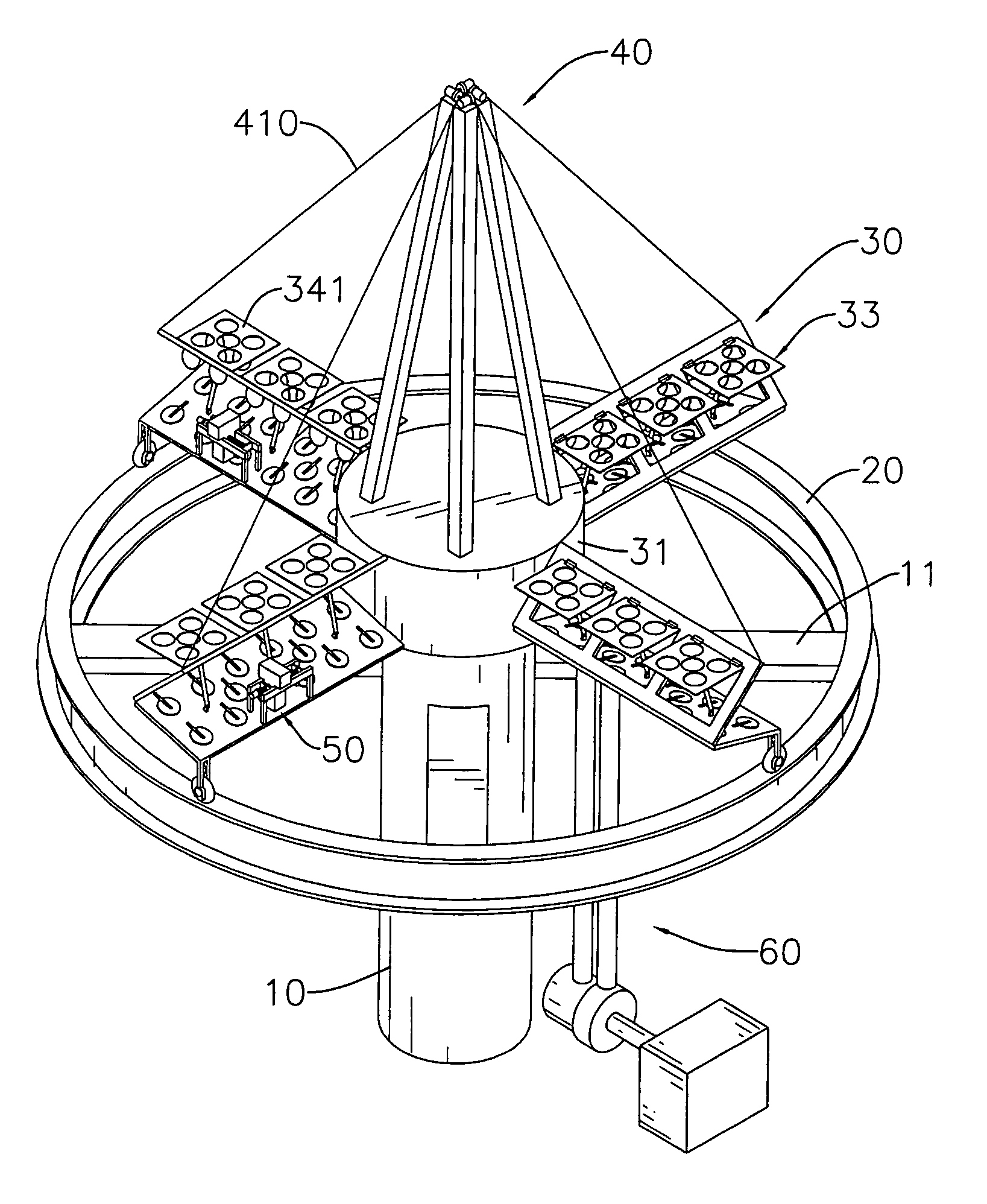
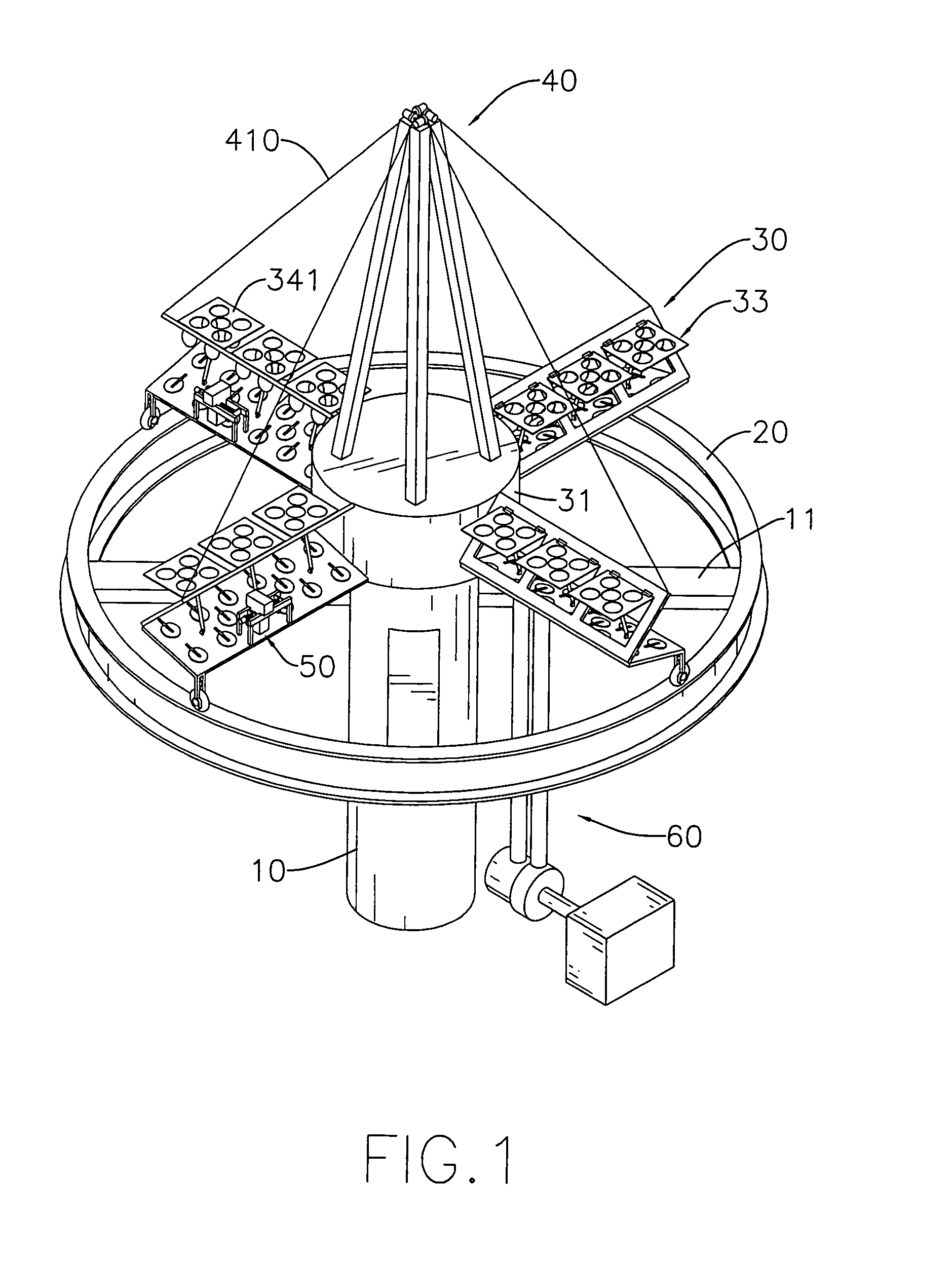
[0020]With reference to FIGS. 1, 2 and 3, the wind generator in accordance with present invention comprises a post (10), a rail (20), a blade assembly (30), a stay assembly (40), a generator assembly (60) and an optional accelerating motor (70).

[0021]The post (10) may be tubular, is securely mounted on a surface of a building, a ground or such like, and has a top and at least two support bars (11) perpendicularly attached diametrically near the top of the post (10).

[0022]The rail (20) is annular and is mounted on the support bars (11) of the post (10).

[0023]The blade assembly (30) is mounted rotatably on the top of the post (10), is pushed by the wind to rotate relative to the post (10) and has a base (31), a bearing (32) and multiple blades (33).

[0024]With further reference to FIG. 6, the base (31) is an open container, may be cylindrical and has a bottom opening (310). The bottom opening (310) is rotatably mounted around the top of the post (10) and has an inner surface and multip...


PUM


Abstract

A wind generator has a post, a rail mounted on the post and a blade assembly mounted rotatably on a top of the post. The blade assembly includes multiple blades radially formed around a base. Each blade has multiple vents, a slat and multiple relief valves. The slat is controllable mounted to open or close the vents, so as to adjust a force of wind applied to the blades. The relief valves are mounted pivotally to selectively cover valve holes formed through the blades to prevent the wind resistance force applied to the blades. Therefore, the wind generator can work in both turbulent and with a low wind force without breaking.

Description

BACKGROUND OF THE INVENTION[0001]1. Field of the Invention[0002]The present invention relates to a generator, and more particularly to a wind turbine that functions at low wind speeds, in turbulent air flows and without being broken at high wind speeds.[0003]2. Description of Related Art[0004]Wind generators are machines for converting kinetic energy from wind into electricity, and are developed into various types to adapt to different circumstances.[0005]A wind generator comprises a post, a blade assembly and a generator. The post is mounted vertically. The generator is mounted on the post to generate electricity. The blade assembly is mounted rotatably on the generator and is rotated horizontally by the wind to allow the generator to function.[0006]However, such kind of wind generators suffer from pulsating torque produced during each revolution and their efficiency is reduced by drag created when the blade rotates into the wind. The wind generators are also inappropriate to mount...

Claims


Application Information

Patent Timeline
IPC IPC(8): F01D15/10
CPCF03D3/005Y02E10/74F03D3/062
Inventor LIAO, FU-CHANG
Owner LIAO FU CHANG
Why Eureka
Try Eureka