Lenticular lens array and image display device including the same

a technology of image display device and lenticular lens, which is applied in the direction of optics, instruments, electrical devices, etc., can solve the problems of increasing power consumption and achieve the effect of low power consumption

Active Publication Date: 2007-12-27
LG DISPLAY CO LTD
View PDF25 Cites 72 Cited by
  • Summary
  • Abstract
  • Description
  • Claims
  • Application Information

AI Technical Summary

Benefits of technology

[0016]An object of the present invention is to provide a lenticular lens array and an image display device using the same that easily converts a 2-D mode into a 3-D mode and a 3-D mode into a 2-D mode with low power consumption.

Problems solved by technology

Therefore, the lenticular lens array type image display device 110 requires a higher driving voltage when compared to the conventional LCD device, leading to increased power consumption.

Method used


Image

  • Lenticular lens array and image display device including the same
  • Lenticular lens array and image display device including the same
  • Lenticular lens array and image display device including the same

Examples


Embodiment Construction

[0029]Reference will now be made in detail to the preferred embodiments of the present invention, examples of which are illustrated in the accompanying drawings.

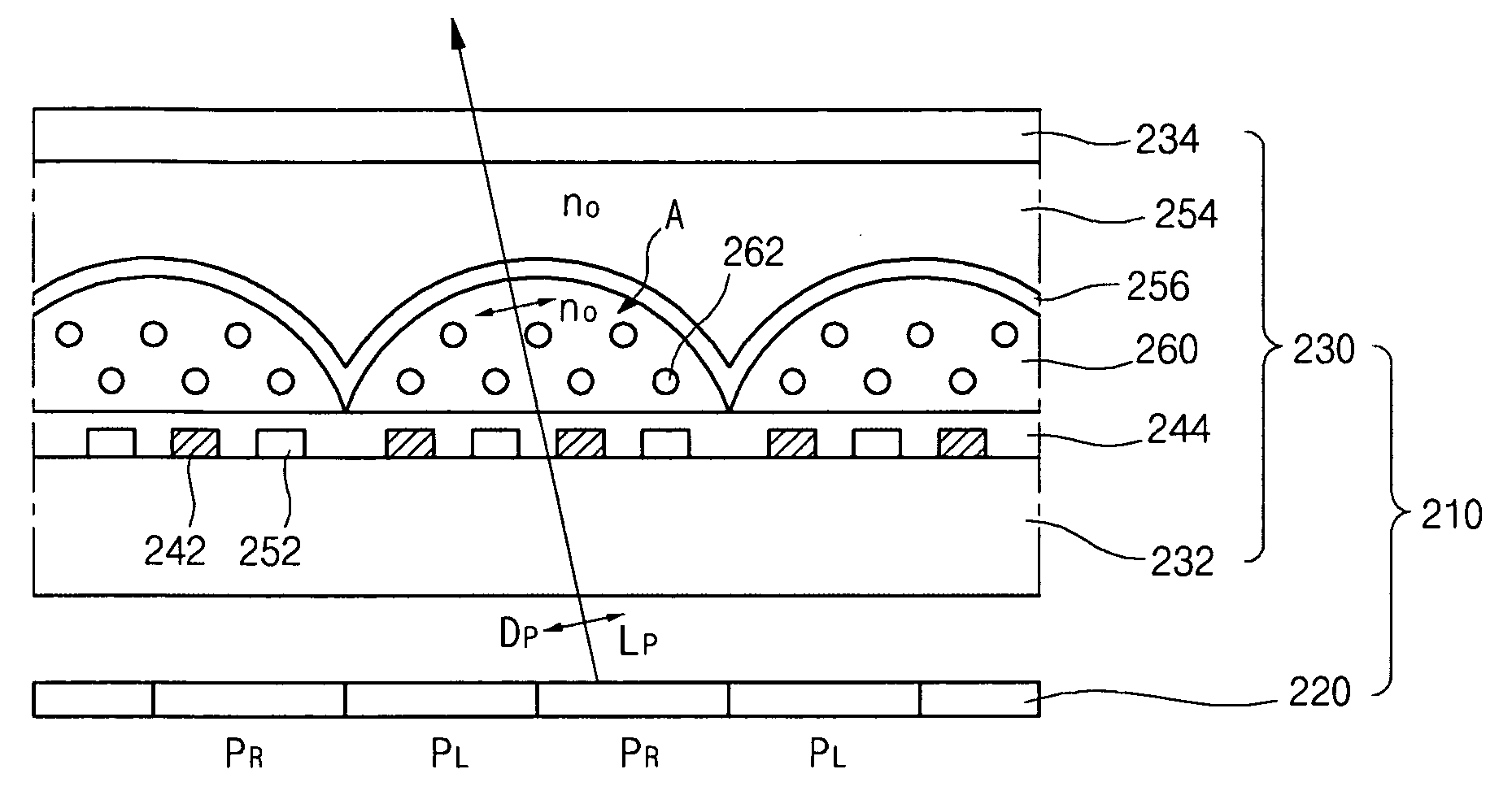
[0030]FIGS. 3A and 3B are cross-sectional views demonstrating an exemplary process of producing a 2-D mode and a 3-D mode, respectively, in a lenticular lens array type image display device according to an embodiment of the present invention. FIG. 4 is a perspective view of the exemplary lenticular lens array type image display device shown in FIGS. 3A and 3B.

[0031]As shown in FIGS. 3A and 3B, the lenticular lens array type image display device 210 according to the present invention includes a display panel 220 and a lenticular lens array 230 over the display panel 220. The display panel 220 includes a first pixel PL and a second pixel PR. The first and second pixels PL and PR are alternately arranged and produce images for left and right eyes, respectively. The lenticular lens array 230 includes first and second substrates ...


PUM

PropertyMeasurementUnit
refractive indexaaaaaaaaaa

Abstract

An image display device includes a display panel, a first substrate over the display panel, a plurality of first electrodes on the first substrate, a plurality of second electrodes alternately arranged with the plurality of first electrodes, a second substrate facing the first substrate, a replica layer on the second substrate and having a concave pattern of half-cylinder shape, the concave pattern facing the second electrode, and a liquid crystal layer in the concave pattern.

Description

[0001]The present application claims the benefit of Korean Patent Application No. 2006-0058232 filed in Korea on Jun. 27, 2006, which is hereby incorporated by reference.BACKGROUND OF THE INVENTION[0002]1. Field of the Invention[0003]The present invention relates to a lenticular lens array and an image display device including the same, and more particularly, to a lenticular lens array type dimension-switchable image display device that is able to switch from a two dimensional mode into a three dimensional mode or from the three dimensional mode into the two dimensional mode.[0004]2. Discussion of the Related Art[0005]A technology of producing three dimensional (3-D) images including 3-D stereoscopic images from two dimensional (2-D) images can be used in display technologies, aerospace technologies, etc. The technology using ripple effects to produce 3-D images can not only be used in applications for high definition televisions (HDTV), but also can be used in a variety of other ap...

Claims


Application Information

Patent Timeline
Patent Type & Authority Applications(United States)
IPC IPC(8): G02F1/1333G02B30/28
CPCG02B3/12G02B27/2214H04N13/0404G02F1/1347G02F2001/294G02F1/133526H04N13/305G02F1/294G02B30/28G02B30/27
Inventor HONG, HYUNG-KILEE, BYUNG-JOOJUNG, SUNG-MINPARK, JU-UNSHIN, HYUN-HO
Owner LG DISPLAY CO LTD
Why Eureka
Try Eureka