Method and apparatus for amplified spontaneous emission corrected automatic signal power control of an optical amplifier

an automatic signal and amplifier technology, applied in the field of optical amplifiers, can solve the problems of inability to determine the usable optical signal power of existing apc implementations

Inactive Publication Date: 2007-12-27
JUMIPER NETWORKS INC
View PDF14 Cites 19 Cited by
  • Summary
  • Abstract
  • Description
  • Claims
  • Application Information

AI Technical Summary

Benefits of technology

[0006]According to another aspect of the present invention, there is provided an optical amplifier system with an optical input and an optical output and a control input comprising: an optical amplifier in a signal path between the optical input and the optical output, operable to amplify an input optical signal to produce an amplified optical signal comprising an amplified input optical signal and amplified spontaneous emission (ASE); a first photodetector operable to measure power of the input optical signal at the optical input; a second photodetector operable to measure power of the amplified optical signal at the optical output; an amplification controller functionally connected to the optical amplifier, the control input and the first and second photodetectors, operable to: determine a target usable signal power; determine an estimate of ASE power in the amplified optical signal; and control the optical amplifier such that the amplified input optical signal at the output of the amplifier has a power substantially equal to the target usable signal power.
[0007]According to still another aspect of the present invention, there is provided a method for controlling an optical amplifier comprising: determining target usable signal power; estimating ASE power in an amplified optical signal comprising an amplified input optical signal and ASE as a function of an input optical signal power and the target usable signal power; and controlling at least one control signal such that the amplified input optical signal at the output of the amplifier has a power substantially equal to the target usable signal power.
[0008]According to yet another aspect of the present invention, there is provided a computer readable medium having recorded thereon statements and instructions for execution by a computer to carry out the method for controlling an optical amplifier comprising: determining target usable signal power; estimating ASE power in an amplified optical signal comprising an amplified input optical signal and ASE as a function of an input optical signal power and the target usable signal power; and controlling at least one control signal such that the amplified input optical signal has a power substantially equal to the target usable signal power.
[0009]According to a further aspect of the present invention, there is provided a controller comprising: a first input operable to receive a measurement of power of an input optical signal of at least one optical amplifier operable to amplify the input optical signal to produce an amplified optical signal comprising an amplified input optical signal and amplified spontaneous emission (ASE); a second input operable to receive a measurement of power of the amplified optical signal of the at least one optical amplifier; control logic operable to: determine a target usable signal power; determine an estimate of ASE power in the amplified optical signal; and provide at least one control signal operable to adjust a gain of the at least one optical amplifier such that the amplified input optical signal has a power substantially equal to the target usable signal power; and at least one control signal output operable to output the at least one control signal.

Problems solved by technology

Therefore, existing APC implementations are unable to determine the usable optical signal power and optical network engineers are forced to allow additional margins in their optical power-budget design or operate the amplifier in automatic gain control (AGC) where an ASE correction is easier to implement.

Method used


Image

  • Method and apparatus for amplified spontaneous emission corrected automatic signal power control of an optical amplifier
  • Method and apparatus for amplified spontaneous emission corrected automatic signal power control of an optical amplifier
  • Method and apparatus for amplified spontaneous emission corrected automatic signal power control of an optical amplifier

Examples


Embodiment Construction

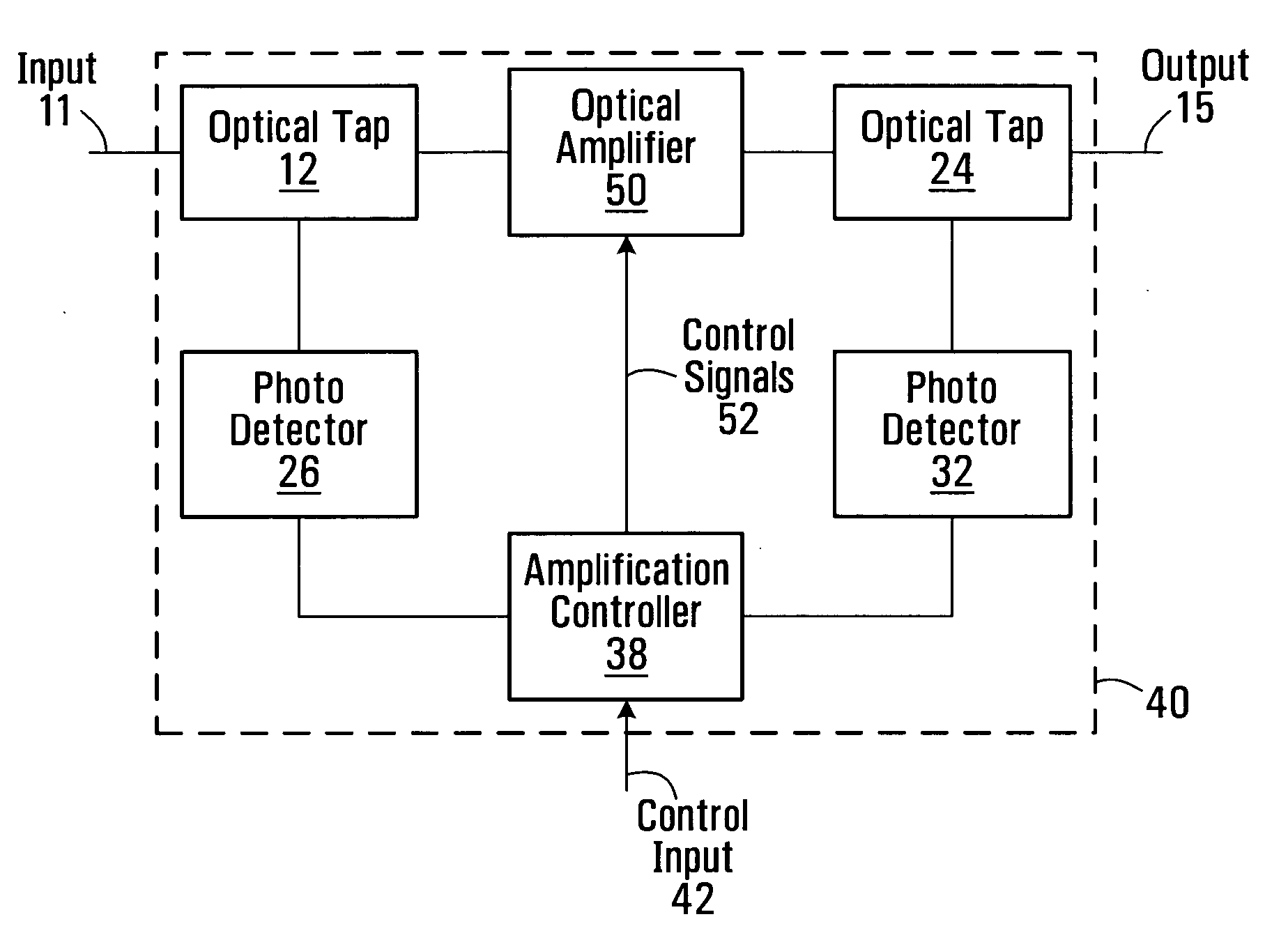
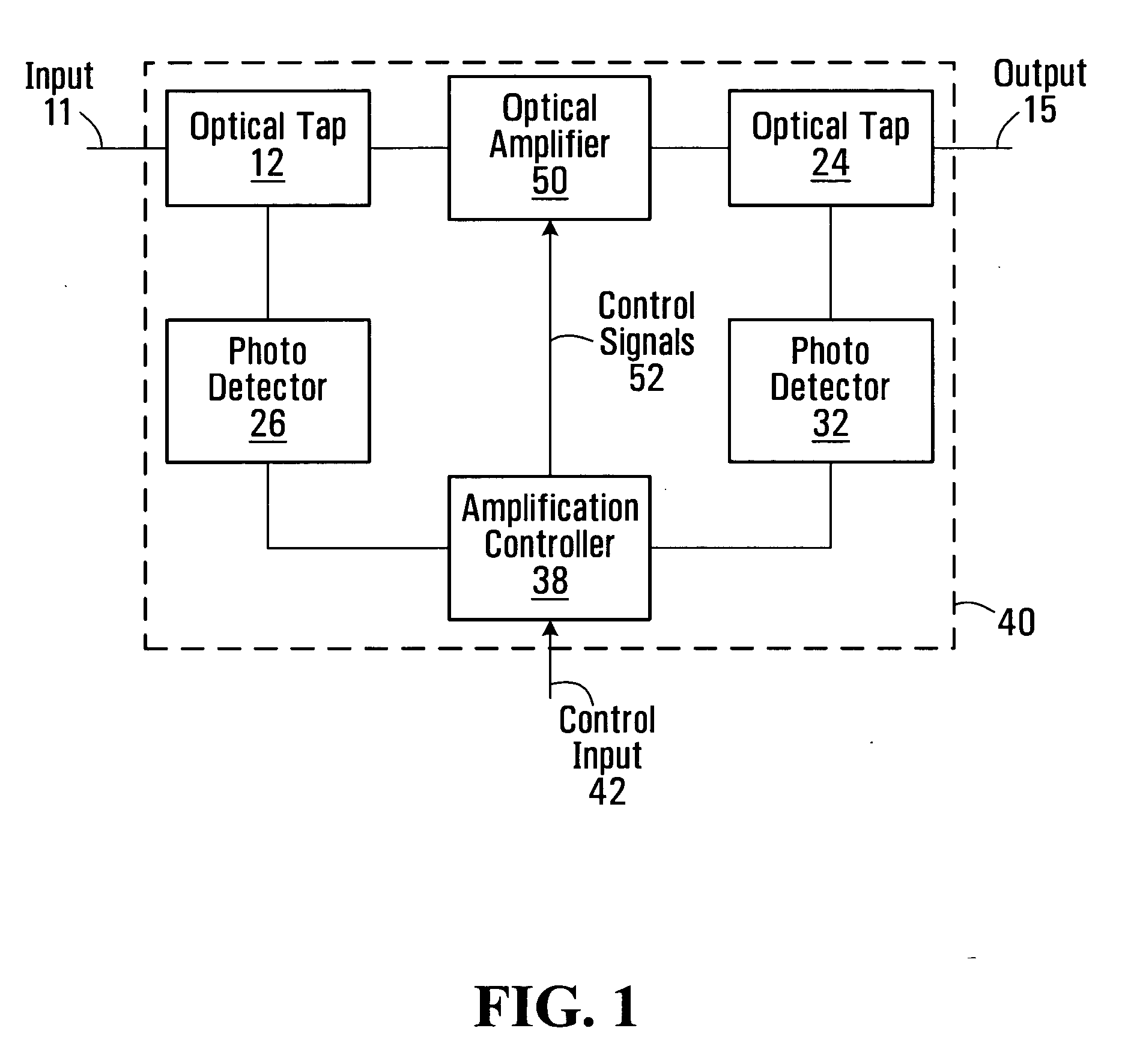
[0021]A system designer who wishes to operate an optical amplifier with APC is generally interested in knowing the useful signal power, not the total power. Unfortunately, existing APC implementations fail to compensate for the ASE power. Because of this, existing APC solutions are of limited value to system designers.

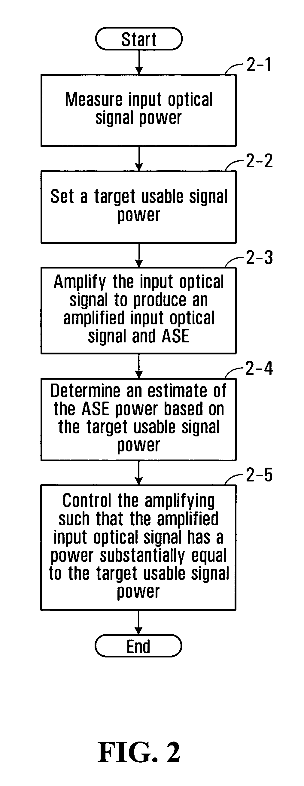
[0022]Various methods and devices to perform amplified spontaneous emissions (ASE) corrected automatic signal power control (ASPC) in an optical amplifier are provided. The methods and devices for doing this make use of measured input and output power levels, and calculate the ASE power for a target output signal power level. A gain of the optical amplifier can then be automatically adjusted in order to keep the output signal power at the target output signal power level regardless of the presence of ASE. The type of optical amplifier that might be used is an implementation specific detail and might include doped fiber amplifiers, such as erbium doped fiber amplifiers,...


PUM


Abstract

An optical amplifier system and controller and a method for automatically controlling the usable signal power of an optical amplifier are provided. The method differentiates between the total optical power that includes the amplified spontaneous emission (ASE), and the useful amplified optical signal power at the output of the amplifier. The optical amplifier system comprises an optical amplifier, a first and a second photodetector operable to measure the power of the input and output signals of the optical amplifier and an amplification controller with a control input. The amplification controller is operable to compensate for the ASE power when operating in automatic signal power control mode.

Description

RELATED APPLICATION[0001]This application claims the benefit of prior U.S. provisional application No. 60 / 805,817 filed Jun. 26, 2006, hereby incorporated by reference in its entirety.FIELD OF THE INVENTION[0002]The invention pertains to the field of optical amplifiers, and more particularly to the field of automatic signal power control of optical amplifiers.BACKGROUND OF THE INVENTION[0003]For many applications, for example in optical pre-amplifiers, it is desirable to operate an optical amplifier in a mode of operation such that either the output optical power of the amplifier or the gain of the optical amplifier is maintained at a constant level. These modes of operation are referred to as constant output power mode and constant gain mode respectively.[0004]The total optical output power of an amplifier consists of both amplified signal power and amplified spontaneous emission (ASE) power. Existing amplifiers rely on automatic power control (APC) to maintain the total optical po...

Claims


Application Information

Patent Timeline
Patent Type & Authority Applications(United States)
IPC IPC(8): H01S3/00
CPCH01S3/06754H01S2301/02H01S3/1305H01S3/1301H01S3/06758H01S3/10015H01S3/13013
Inventor QIAO, LIJIEVELLA, PAUL J.
Owner JUMIPER NETWORKS INC
Why Eureka
Try Eureka