
Video distribution system

a technology of video distribution system and key value, applied in the field of video distribution system, can solve the problems of increasing the amount of storage memory required, increasing the work and effort required to store the many key values beforehand, and taking more time and effort, so as to achieve efficient setting and managing the key value

Inactive Publication Date: 2007-12-27
KOKUSA ELECTRIC CO LTD
View PDF11 Cites 99 Cited by
  • Summary
  • Abstract
  • Description
  • Claims
  • Application Information

AI Technical Summary

Benefits of technology

The invention provides a video distribution system that uses hierarchical keys to encrypt and decrypt video data. By using a system of keys and elements, the number of keys that need to be set and stored is reduced, making it easier for system administrators to manage. The video distribution system includes a transmitter and a receiver, with the transmitter generating the highest-order key and the elements needed to generate the lowest-order key. The receiver uses the highest-order key to generate the lowest-order key and decrypt the video data. The system may use different types of keys and elements for different data types. The invention also includes a store-and-forward apparatus for temporarily storing and transmitting the data and elements. The technical effects of the invention include reducing the number of keys needed to be set and stored, simplifying the administration of hierarchical keys, and improving security.

Problems solved by technology

In such a case, when there are many video transmitters 3, the work and effort required to store the many key values beforehand are increased, and the amount of storage memory required is also increased, which has been a problem.
When encryption keys are changed numerous times, it requires that many decryption keys be set in the video receiver 4, which has been a problem in that it takes more time and effort and increases the amount of storage memory needed.
Moreover, assuming that each video transmitter 3 is a device that continuously transmits video and audio data in units of several tens of milliseconds, changing the encryption key in the video transmitter 3 must be timed with a precision measured in milliseconds, which is difficult and complex, and sometimes impossible.
However, a large number of setting and saving operations imposes a major burden on the system administrator.
In addition, as a result of advances in cryptanalysis technology, the data length of key values is constantly increasing, so that storing numerous keys has become a major burden for some systems equipment.

Method used


Image

  • Video distribution system
  • Video distribution system
  • Video distribution system

Examples


Embodiment Construction

[0048] An embodiment of the invention will now be described with reference to the drawings.

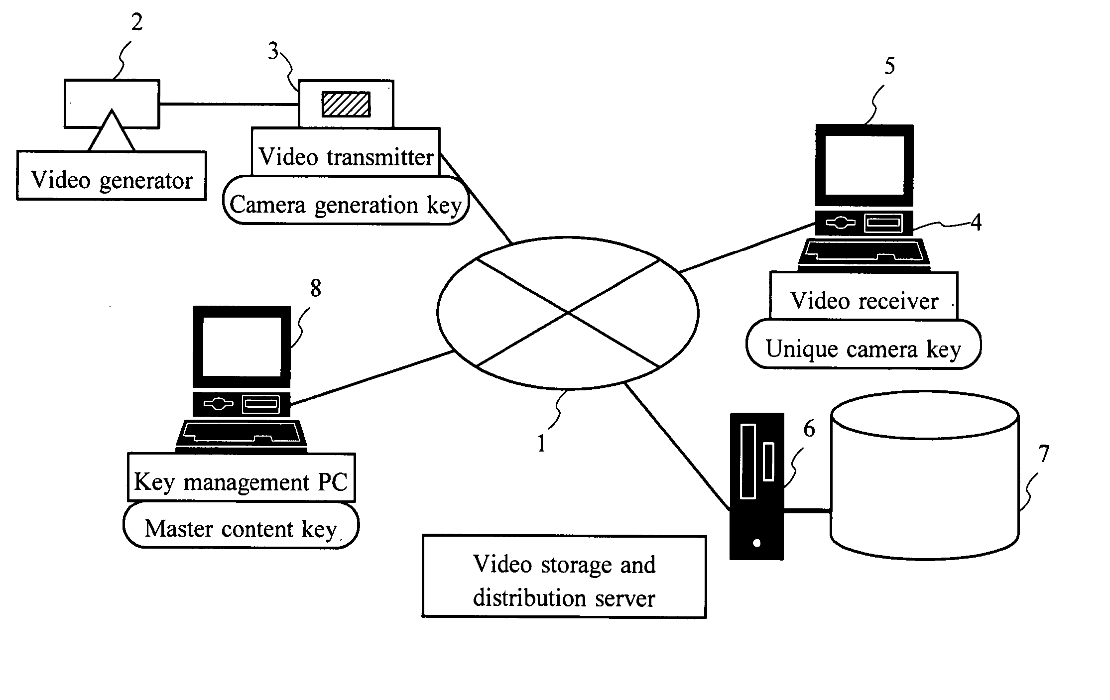
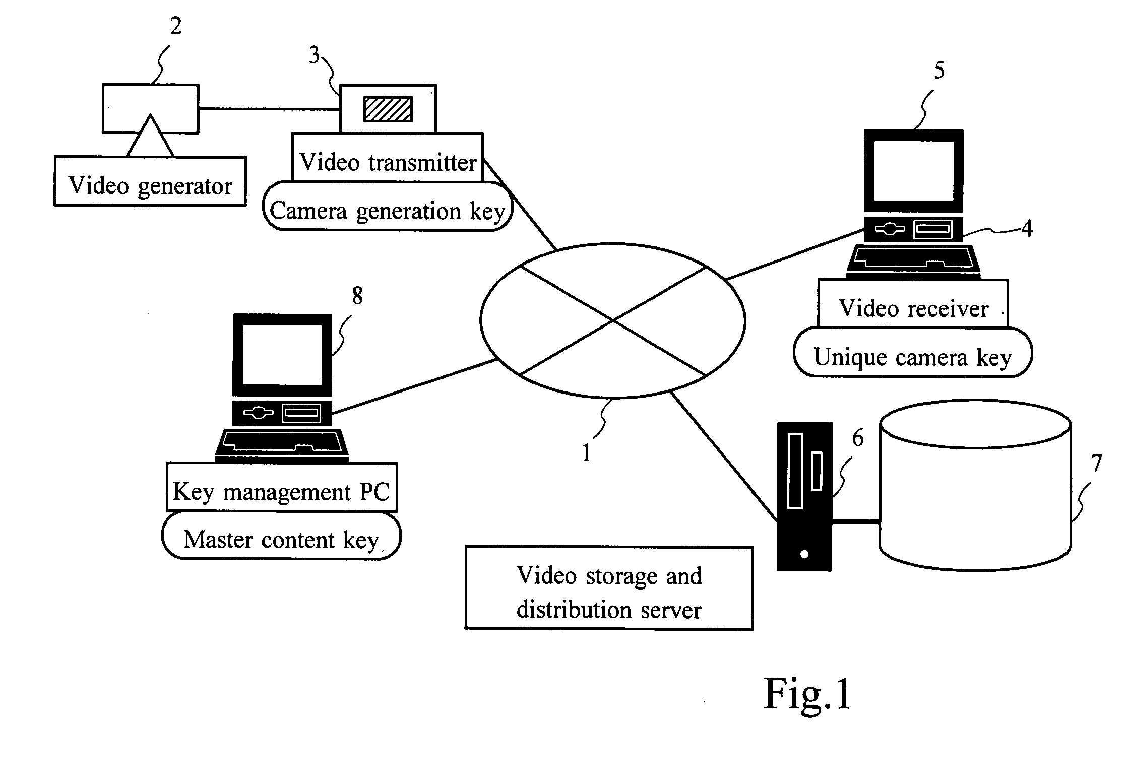
[0049]FIG. 1 shows the arrangement of an embodiment of the video distribution system of the invention. In the case of this system, the encrypted video data from the transmitter can be inspected at the receiving end, and therefore can be used as an encrypted network type video monitoring system. In the arrangement shown here in which audio is transmitted along with the video, the video data includes an audio data component. However, it is also possible to use a configuration in which the video and audio data are transmitted separately. While this embodiment is explained with specific reference to video data, the same processing can be applied to audio and other types of data.

[0050] The video distribution system comprises a network medium 1, a video generator 2, a video transmitter 3, a video receiver 4, a video display unit 5, a video storage and distribution server 6, a recording medium 7 an...


PUM


Abstract

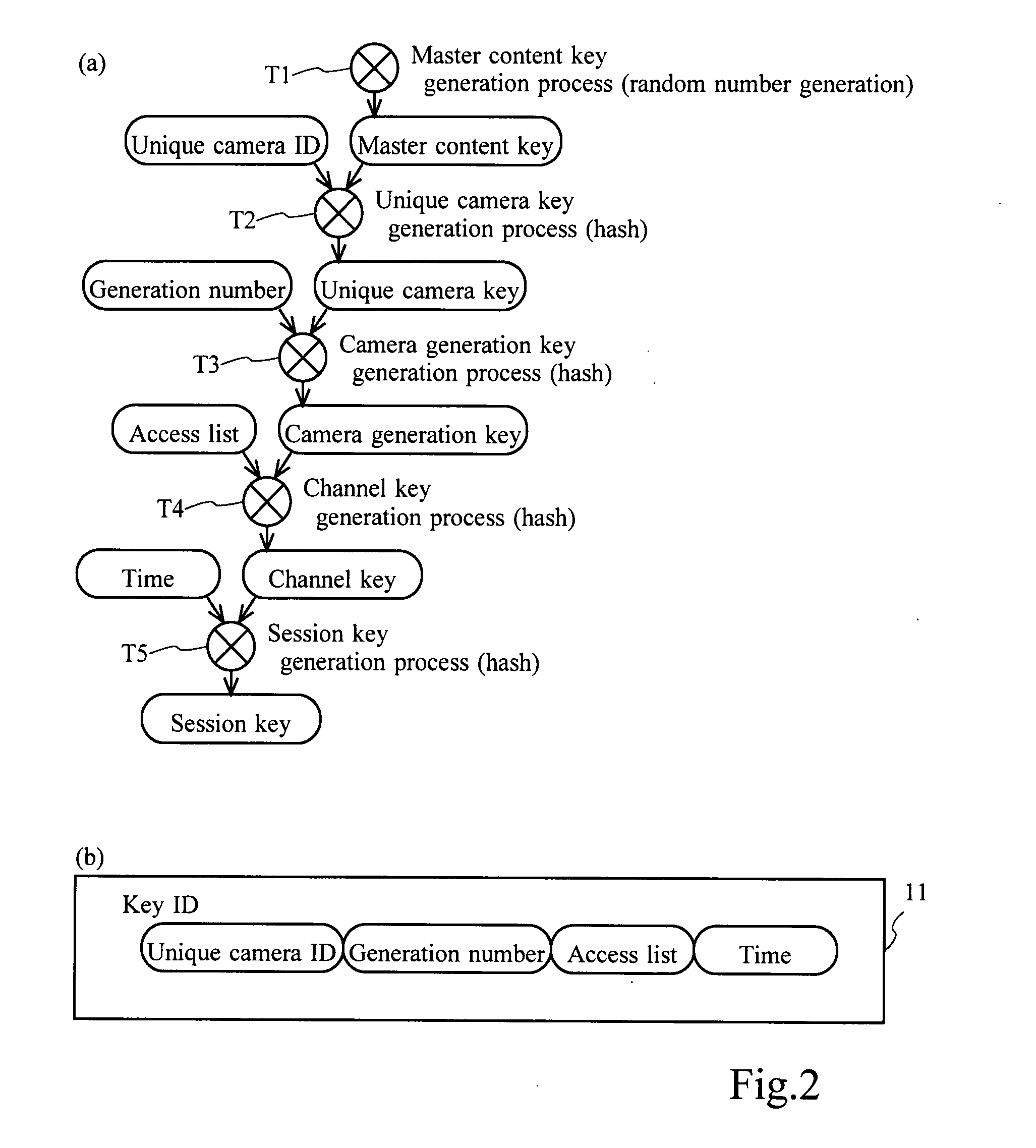
A video distribution system that distributes encrypted video data, using improved encryption keys. A master content key is set as the highest-order key. One or more elements (unique camera ID, generation number, access list, time), and the order thereof, are set for the generation of keys (unique camera key, camera generation key, channel key, session key) that are of a lower order than the highest-order key. A hierarchical key system is used that is implemented by using element by element to generate keys of a gradually lower order than the highest-order key in accordance with the set order of the elements. The lowest-order key (session key) is used for data encryption and decryption.

Description

BACKGROUND OF THE INVENTION [0001] 1. Field of the Invention [0002] This invention relates to a video distribution system that encrypts video images taken by a video camera such as a monitoring camera and transmits, receives and records the video images. It particularly relates to a video distribution system that uses an improved key for encryption. [0003] 2. Description of the Prior Art [0004] To prevent criminal activities and accidents, video monitoring systems are installed in hotels, convenience stores, financial institutions and other such premises, and on public facilities such as dams and roads. These video monitoring systems perform the monitoring using video cameras from which video pictures are transmitted to a monitoring center, such as a control or security room, where the video images are inspected and action taken as required, and the video may also be recorded and stored. [0005] In recent years, network type video monitoring systems are becoming more widespread in wh...

Claims


Application Information

Patent Timeline
Patent Type & Authority Applications(United States)
IPC IPC(8): H04N7/167H04L9/00H04L9/08H04N21/4623
CPCG06F21/606H04N2005/91307H04L63/0428H04L63/068H04N5/76H04N5/772H04N7/1675H04N21/2347H04N21/25816H04N21/25833H04N21/25875H04N21/26613H04N21/4405H04N21/835H04N21/8352G08B13/19656H04N5/913H04N7/167H04N2005/91364H04L63/064H04L9/08H04N7/18H04N21/6334
Inventor OGURA, SHINYANAKABAYASHI, SUMIE
Owner KOKUSA ELECTRIC CO LTD
Learn More